So What Processor Was Used in Brick Game? Part 2
Continuing the investigation into Brick Game handheld consoles, the author decapsulates microcontroller dies, reads ROM contents through an optical microscope, and builds a working emulator from the recovered firmware.
Editor's Context
This article is an English adaptation with additional editorial framing for an international audience.
- Terminology and structure were localized for clarity.
- Examples were rewritten for practical readability.
- Technical claims were preserved with source attribution.
Source: the original publication
By the time the previous article was written, more test subjects were already on their way to me, and the first one I received was this:

Brick Games like this one started appearing for sale around the late 2000s. On this one I tried a new method of die decapsulation, fearing a repeat of the previous failure. The approach is as follows: a drop of epoxy compound is heated with a heat gun until it becomes soft but not yet brittle (around 150 degrees). Without stopping the heating, you carefully pry the compound with a scalpel and try to peel it off — first from the PCB, and then, with extra caution, from the die itself. It sounds fairly simple, but in practice it's not. Although I succeeded three times out of three, the risk of damaging the die with a careless tweezer movement is still high. The upside is there's no need for any chemicals, which is very convenient for home conditions.
So, here is the die of the first Brick Game:

As expected, the process node is much denser. Unfortunately, there are no identifying marks — only the number 2008, which is most likely the year the mask was created.
I won't attempt a deep analysis, but briefly: in the upper right corner there's 7.5 KB of ROM (which I think would be extremely difficult to read visually through an optical microscope), below it 384 bytes of RAM. In the upper left corner, apparently, is the instruction decoder (which could potentially be used to identify the microcontroller). I may be wrong, but I'll hypothesize that this is an 8-bit microcontroller that has nothing to do with the HT-443.
The next Brick Game came to me as a pile of internals, so I don't know what it looked like in its better days. The PCB is dated 12/8/2002, and judging by the button layout, this is a typical "1 in 9999" from the early 2000s. Here's a photo of its die:

Absolutely the same architecture and almost the same die area, just with a somewhat different layout. 3 KB ROM, 160 bytes RAM. Again, no identification whatsoever — only the year(?) — 2003.
And here is the main guest of honor, with the modest name Super Brick Game E-23 PLUS MARK II 96 IN 1 from the Taiwanese company E-Star:

The epoxy blob on this one was much larger than the previous two, so the decapsulation took me half an hour, but the result was worth it:

Good old HT-943 (also known as HT443A0), just one year older than the specimen from the previous article.
For a die size comparison, I took a group photo:
")
Drawing conclusions from just four specimens is premature, of course, but one can hypothesize that the main Brick Game platform in the early and mid-1990s, when they were still manufactured in Taiwan, was Holtek's 4-bit microcontrollers. By the late '90s and early 2000s, when such toys started being mass-produced in China, the main platform shifted to something closer to the local fabs.
Reading the ROM
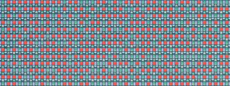
Naturally, I was most interested in the ROM, but the first look was disappointing — practically unreadable:

Fortunately, it turned out that illuminating the die at an angle yields much better results, though still not perfect:

Now the boundaries of transitions from "normal" transistors to those with increased gate oxide thickness are clearly visible. The increased oxide thickness raises the transistor's threshold voltage to a level where it never turns on (you can consider it as absent). In the following image, red dots mark the "normal" transistors whose gate oxide layer allows them to be turned on by the decoder's selection signal:
So how do we turn this mess of bits into a byte sequence — in other words, obtain a ROM dump that can be worked with further?
In the previous article I touched on this topic briefly, but I'll try to explain in more detail here, especially since the task turned out to be harder than I expected.
Let's examine the ROM and its immediate surroundings more closely:
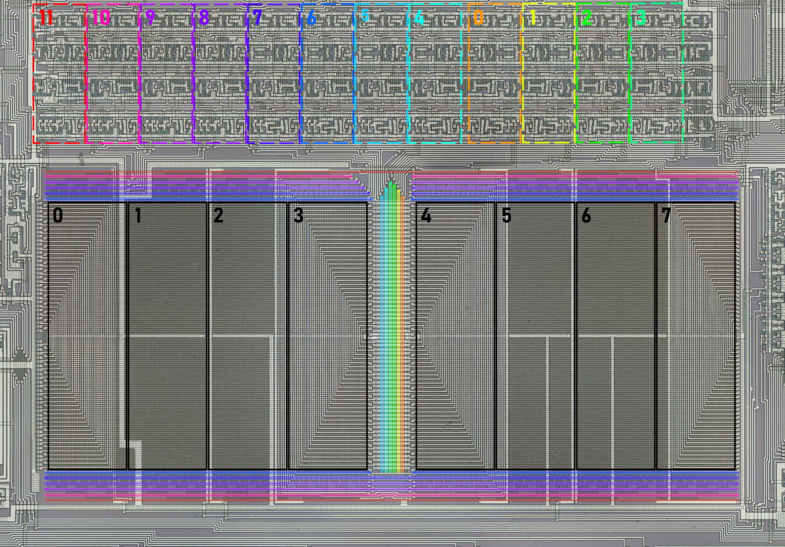
As I noted before, bits of a single byte position are clustered in groups, marked with black rectangles in the image above. To read a byte correctly, you need to determine the bit significance. To do this, you can trace the internal bus (to which each group is connected) to the instruction decoder, where significance is recovered via the instruction descriptions in the datasheet. The bit position determined this way is labeled with a number in the image.
At the top, you can identify 12 repeating transistor groups (marked with colored rectangles), each sending a pair of signals — direct and inverted — to the decoder lines around the ROM (marked with colored lines matching their groups). It's natural to assume that these lines define the 12-bit address of the byte being read, and that the transistor groups form the program counter registers, stack (single-level here), and some auxiliary logic. To read bytes in the correct order, you again need to determine how the decoder lines correspond to address bit positions. This is somewhat more complex than the data bit case. All 12 bits are connected to the 8-bit internal bus whose bit significance we've already established. Some bits (the left and right four groups) share the lower bus bits between them. I additionally had to analyze the register control lines — they fully match for the rightmost eight groups but differ for the four leftmost ones. This means the four left address bits are loaded into the program counter separately from the right eight, leading me to conclude they are the high bits. Address bit numbers are also labeled in the image.
There are two things I couldn't determine without a detailed schematic reconstruction: which line of each decoder pair carries the direct signal and which the inverted one, and the same for the data bits. This gives us 2 possible reading orders and 2 possible byte interpretations — quite manageable.
In practice, however, I ran into some problems. I manually read about a dozen bytes of each variant, disassembled them, and didn't see what I expected. Based on the datasheet, I expected to find something like an unconditional jump at address zero where the microcontroller starts after reset. I also expected unconditional jumps at addresses 4 and 8 where interrupts land — or at least a reti if they're unused. But no — one variant was stranger than the next, and I had to check a bunch of other, less likely reading orders that didn't fit the theory described above. Having achieved nothing, I ultimately chose one of the first four variants that looked more or less reasonable and continued reading the ROM, gradually convincing myself it was indeed the correct reading order — the firmware authors simply ignored interrupts entirely and used some rather unexpected instructions like decrementing a memory cell right at startup and outputting 0xE to port PA, which isn't physically connected to anything:
000:    dec [R3R2]                      ;0F
001:    timer on                        ;38
002:    mov A, 0xE                      ;7E
003:    out PA, A                       ;30
004:    mov R1R0, 0xFF                  ;5F0F
006:    in A, PP                        ;34
007:    ja0 04C                         ;804C
009:    mov A, 0xF                      ;7F
00A:    call E67                        ;FE67
00C:    jmp 002                         ;E002
The Emulator
Having confirmed I was on the right track, I continued deciphering the ROM while simultaneously debugging an emulator I had started writing a bit earlier. After several days of this work, the firmware was fully recovered, the emulator was generally debugged, and obvious ROM dump errors were corrected. Finally, I saw the cherished "01" on the display, experiencing feelings roughly similar to those of Victor Frankenstein screaming "It's alive!"


Of course, it wasn't this pretty at first — at that point I had only added part of the playing field's display segments. By the way, while reconstructing the segment map, I was amazed at how non-uniformly they're laid out: one digit's segments are addressed one way, the neighboring digit another way, part of the playing field one way, another part differently — I don't envy the programmers who wrote code for this display.
The emulator is still rough around the edges (for example, there's no sound at all), and I'm not sure I'll polish it, but even now it can help with firmware research, if anyone is interested in writing their own emulator or hunting for possible easter eggs. You can also just play and feel nostalgic :) The application supports basic debugging tools, and the contents of all registers and RAM can be changed on the fly. It's written in Python using PyQt6, so it can run on all operating systems supported by that library (Linux, Windows, and macOS). Source code is available on GitHub, where you can also find the firmware image.
There are most likely still errors, so if you have the same Brick Game model and notice behavioral differences from the original, please let me know — I'll try to fix them.
Continuation
Why This Matters In Practice
Beyond the original publication, So What Processor Was Used in Brick Game? Part 2 matters because teams need reusable decision patterns, not one-off anecdotes. Continuing the investigation into Brick Game handheld consoles, the author decapsulates microcontroller dies, reads ROM contents through an...
Operational Takeaways
- Separate core principles from context-specific details before implementation.
- Define measurable success criteria before adopting the approach.
- Validate assumptions on a small scope, then scale based on evidence.
Quick Applicability Checklist
- Can this be reproduced with your current team and constraints?
- Do you have observable signals to confirm improvement?
- What trade-off (speed, cost, complexity, risk) are you accepting?


