Understanding the NTSC Composite Video Signal, and Whether It's Worth Studying in 2025. Part 2
A deep technical dive into software generation of NTSC composite video signals using a Raspberry Pi Pico microcontroller, covering DMA, PIO, R2R DAC circuits, color palette generation, and ping-pong buffering for real-time signal output.
Introduction
This article continues the exploration of NTSC composite video signals, focusing on practical software generation using microcontrollers. While the previous part covered NTSC fundamentals, this installment dives into implementation on a Raspberry Pi Pico (RP2040), demonstrating how to generate a standards-compliant color video signal entirely in software.
Hardware Requirements
The project uses:
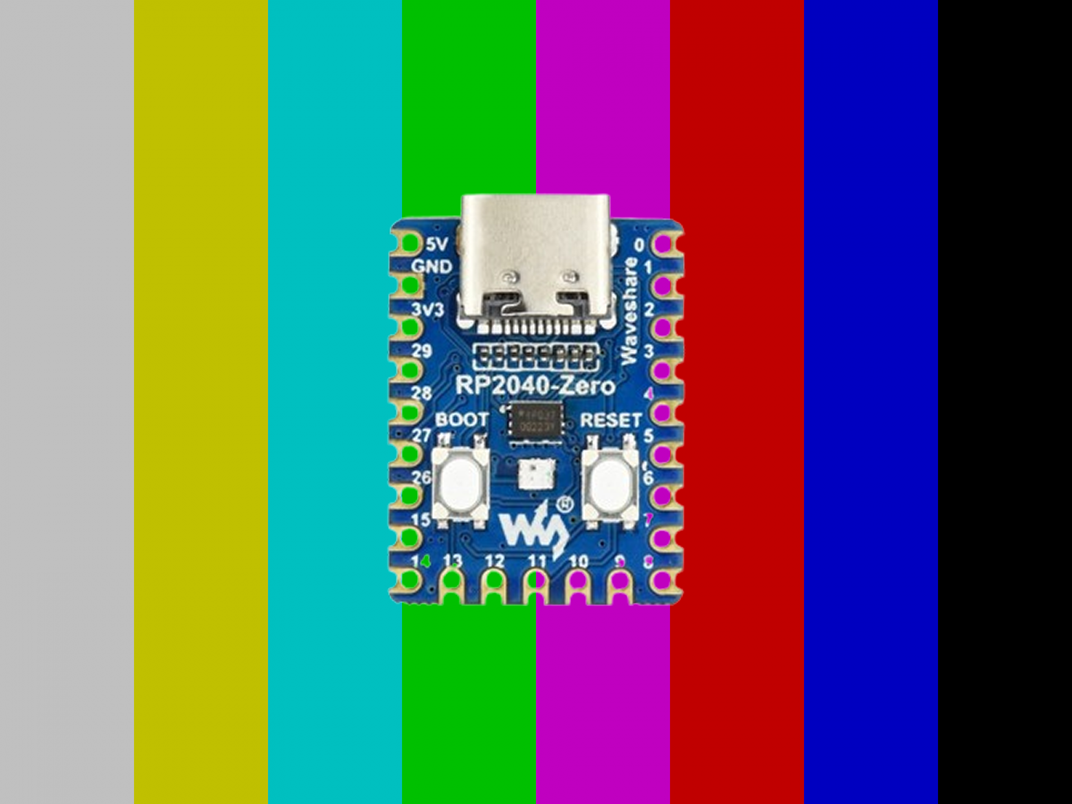
- Raspberry Pi Pico or RP2040-based boards (original recommended over Chinese clones due to voltage stability issues)
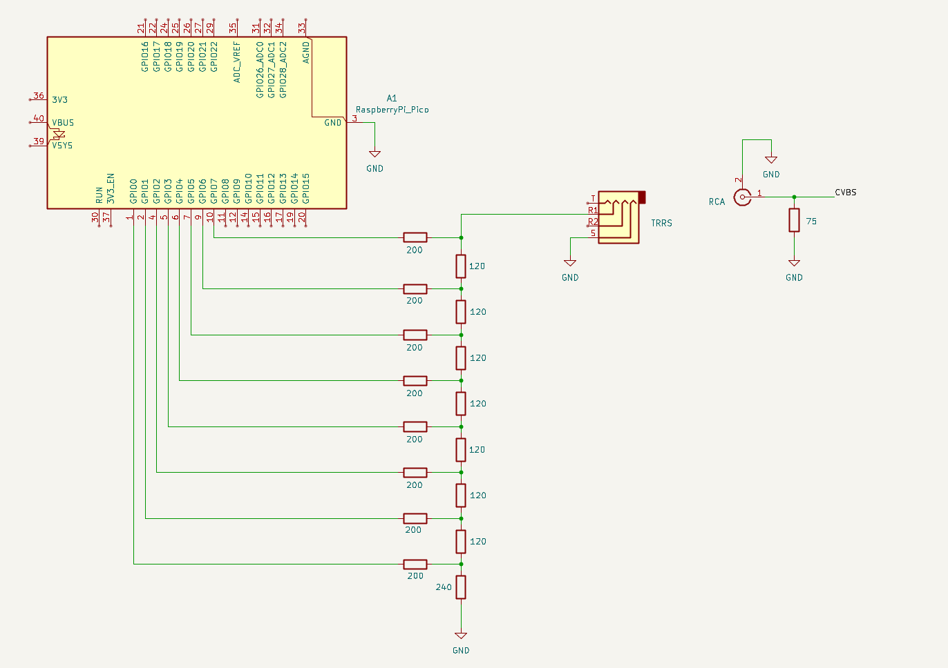
- R2R Ladder DAC for digital-to-analog conversion
- TRRS or RCA connector for output to a TV or capture card
Signal Discretization Requirements
The sampling frequency is set at fd = 4 x fsc = 14.31818 MHz, meeting the Nyquist-Shannon theorem requirements for NTSC signals whose spectrum extends up to 4.2 MHz. This means we output exactly 4 samples per color subcarrier cycle, which greatly simplifies the color encoding math.
Key signal parameters implemented:
- Horizontal interval: 63.556 microseconds
- Active video: 52.656 microseconds
- Vertical lines per field: 262
- Total frame lines: 525
Three Critical Technologies
1. PIO (Programmable I/O)
The RP2040's PIO subsystem outputs 8-bit values to GPIO pins with hardware-controlled timing. The PIO program is remarkably simple:
.program pio_serialiser

.wrap_target
      out pins, 8
.wrap
This single instruction outputs 8 bits to GPIO pins, repeating indefinitely while the FIFO contains data. The initialization code configures the pins and clock divider:
static inline void pio_serialiser_program_init(PIO pio, uint sm, uint offset,
    uint data_pin, float clk_div) {
    for (int i = 0; i < 8; i++ ){
        pio_gpio_init(pio, data_pin + i);
    }
    pio_sm_set_consecutive_pindirs(pio, sm, data_pin, 8, true);
    pio_sm_config c = pio_serialiser_program_get_default_config(offset);
    sm_config_set_clkdiv(&c, clk_div);
    sm_config_set_out_pins(&c, data_pin, 8);
    sm_config_set_out_shift(&c, true, true, 8);
    sm_config_set_fifo_join(&c, PIO_FIFO_JOIN_TX);
    pio_sm_init(pio, sm, offset, &c);
    pio_sm_set_enabled(pio, sm, true);
}
2. DMA (Direct Memory Access)
DMA transfers signal data from RAM to PIO without CPU intervention, enabling precise timing at 14+ MHz. The configuration sets up 16-bit transfers from scanline buffers to PIO FIFO with DREQ gating:
int init_dma_channel(int dma_channel, uint16_t *scanline_buffer,
                     uint chain_to) {
  dma_channel_config channel_config =
      dma_channel_get_default_config(dma_channel);
  channel_config_set_transfer_data_size(&channel_config, DMA_SIZE_16);
  channel_config_set_read_increment(&channel_config, true);
  channel_config_set_write_increment(&channel_config, false);
  channel_config_set_dreq(&channel_config, DREQ_PIO0_TX0);
  channel_config_set_chain_to(&channel_config, chain_to);
  dma_channel_configure(
      dma_channel, &channel_config,
      &pio0_hw->txf[0],
      scanline_buffer, NTSC_SAMPLES_PER_LINE,
      false // Don't start yet
  );
}
3. Interrupt Handlers for Ping-Pong Buffering
While one buffer transmits via DMA, the CPU calculates the next scanline into an alternate buffer. After transmission completes, roles reverse -- maintaining continuous output without gaps.
static void init_interrupt_handler() {
  dma_set_irq0_channel_mask_enabled(
      1u << ntsc_dma_chan_primary | 1u << ntsc_dma_chan_secondary, true);
  irq_set_exclusive_handler(DMA_IRQ_0, ntsc_dma_irq_handler);
  irq_set_enabled(DMA_IRQ_0, true);
}
static void __time_critical_func(ntsc_dma_irq_handler)() {
const volatile uint32_t interrupt_flags = dma_hw->ints0;
dma_hw->ints0 = interrupt_flags;
const uint8_t scanline_buffer_index =
interrupt_flags & (1u << ntsc_dma_chan_secondary) ? 1 : 0;
buffer_handler(scanline_buffer_index);
if (scanline_buffer_index) {
dma_channel_set_read_addr(ntsc_dma_chan_secondary,
ntsc_scanline_buffers[scanline_buffer_index],
false);
} else {
dma_channel_set_read_addr(ntsc_dma_chan_primary,
ntsc_scanline_buffers[scanline_buffer_index],
false);
}
}
Color Palette Generation
The code implements a color palette lookup with calculated CVBS signal values for four subcarrier phases (0 degrees, 90 degrees, 180 degrees, 270 degrees). The luminance formula is:
Y = 0.587*G + 0.114*B + 0.299*R
Chroma components are computed using blue and red color differences weighted by phase angles. The original NTSC formula is: signal = Y + 0.4921*(B-Y)*sin(theta) + 0.8773*(R-Y)*cos(theta).
static void ntsc_set_color(const uint8_t palette_index, const uint8_t blue,
                           const uint8_t red, const uint8_t green) {
  const double luminance = (0.587 * green + 0.114 * blue + 0.299 * red);

  const double blue_chroma_0 = (blue - luminance) * 0.4921 * 0;
  const double red_chroma_0 = (red - luminance) * 0.8773 * 1;
  const double blue_chroma_90 = (blue - luminance) * 0.4921 * 1;
  const double red_chroma_90 = (red - luminance) * 0.8773 * 0;

  // Phase 0: Y + chroma
  int32_t composite_signal =
      (int32_t)(NTSC_SCALE_Y * (luminance + blue_chroma_0 + red_chroma_0) +
                NTSC_SETUP_IRE) * DAC_SCALE + NTSC_LEVEL_BLANK_DAC;
  ntsc_palette[palette_index * 4] = composite_signal < 0 ? 0 : composite_signal;

  // Phase 90, 180, 270 follow the same pattern...
}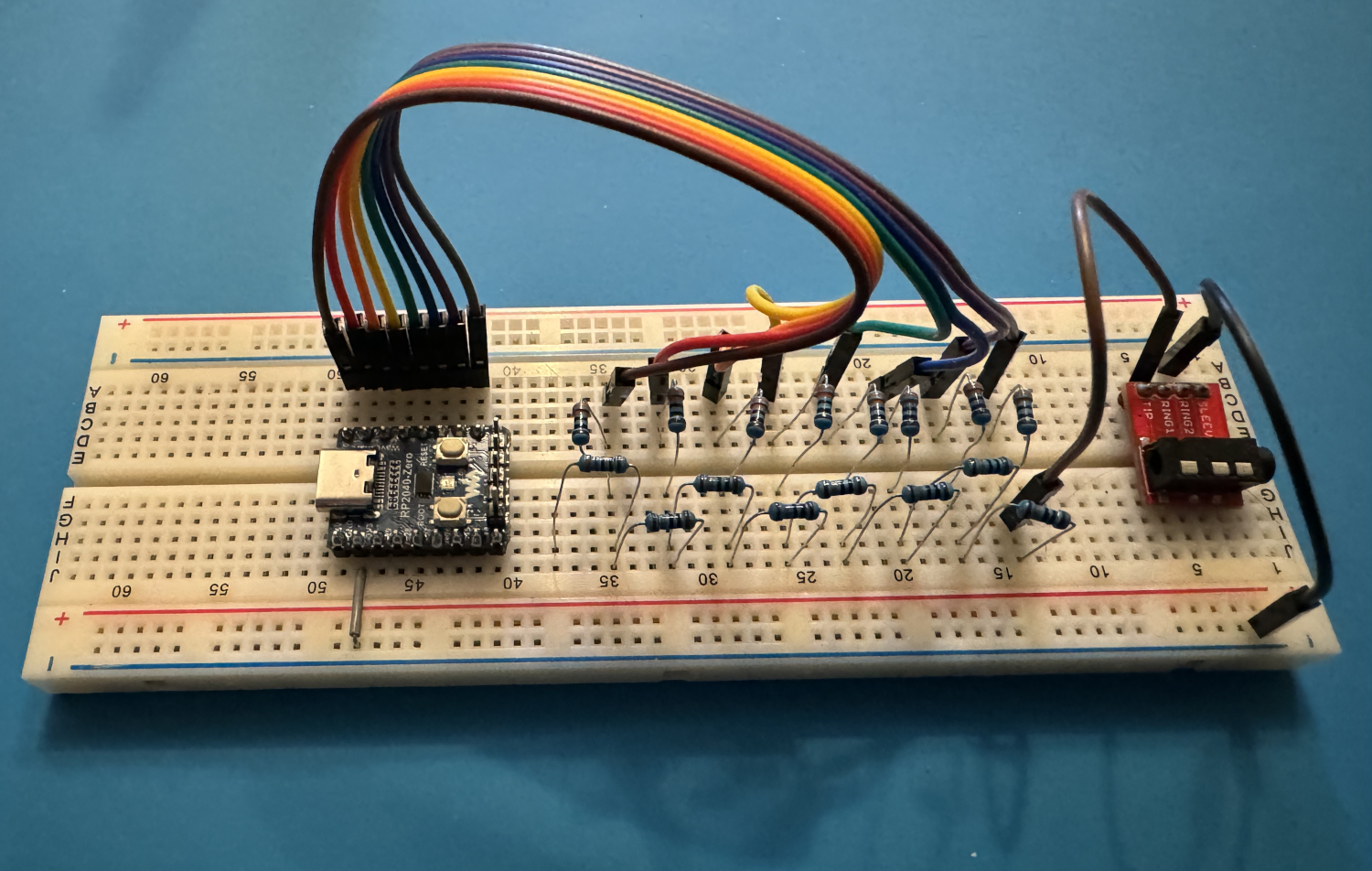
Electronic Circuit
Resistor values were calculated for 1.22V output (171 IRE standard):
- R1 (DAC series resistance): 120 ohms
- 2R ladder resistors: 200 ohms
- Load resistor to ground: 240 ohms
System Initialization
The initialization function overclocks the RP2040 to 157.5 MHz (from the default 125 MHz) and increases the core voltage to 1.30V for stability:
static inline void ntsc_init() {
  const uint32_t system_clock_khz = 157500;
  vreg_set_voltage(VREG_VOLTAGE_1_30);
  set_sys_clock_khz(system_clock_khz, true);

  init_pio();

  ntsc_dma_chan_primary = dma_claim_unused_channel(true);
  ntsc_dma_chan_secondary = dma_claim_unused_channel(true);
  init_dma_channel(ntsc_dma_chan_primary, ntsc_scanline_buffers[0],
                   ntsc_dma_chan_secondary);
  init_dma_channel(ntsc_dma_chan_secondary, ntsc_scanline_buffers[1],
                   ntsc_dma_chan_primary);

  init_interrupt_handler();
  start_dma();
}
Scanline Generation
Each scanline is generated based on its position in the frame. Lines 0-2 and 6-8 are equalizing pulses, lines 3-5 are vertical sync, and the remaining lines contain either blank or active video:
static inline void ntsc_generate_scanline(uint16_t *output_buffer,
                                          const size_t scanline_number) {
  uint16_t *buffer_ptr = output_buffer;
  switch (scanline_number) {
  case 0: case 1: case 2:
  case 6: case 7: case 8:
    equalizing(buffer_ptr);
    break;
  case 3: case 4: case 5:
    vertical_sync(buffer_ptr);
    break;
  default:
    if (scanline_number < NTSC_ACTIVE_VIDEO_START_LINE ||
        scanline_number >= NTSC_ACTIVE_VIDEO_START_LINE + NTSC_FRAME_HEIGHT) {
      blank_line(buffer_ptr);
    } else {
      active_video(buffer_ptr, scanline_number);
    }
  }
}
Testing Equipment
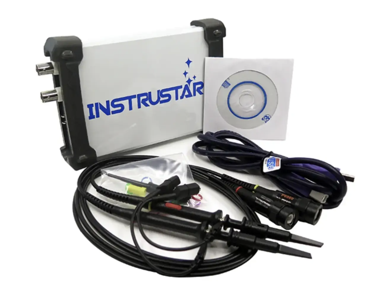
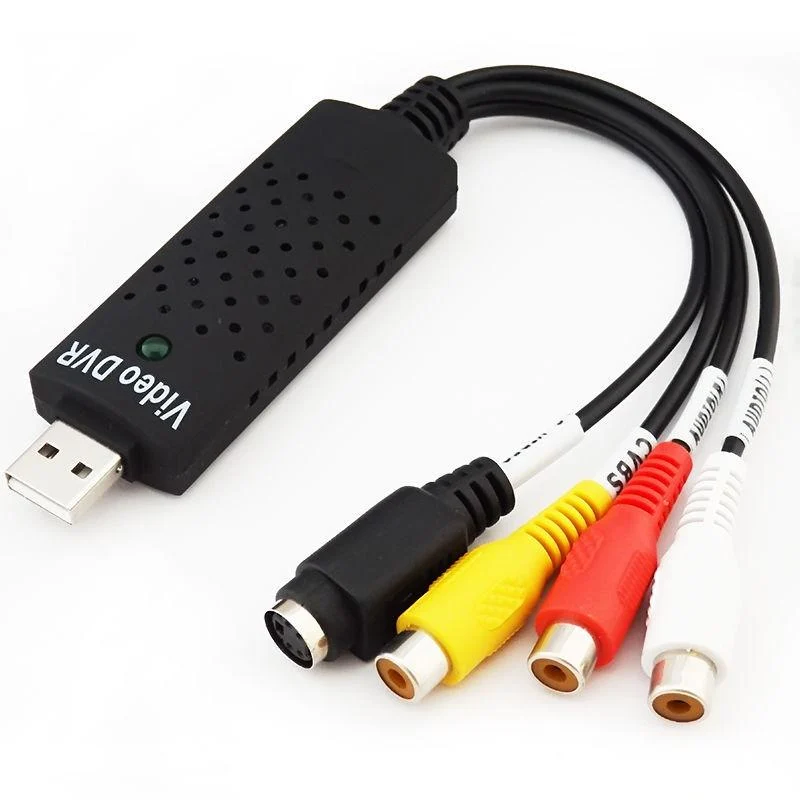
The results were verified using:
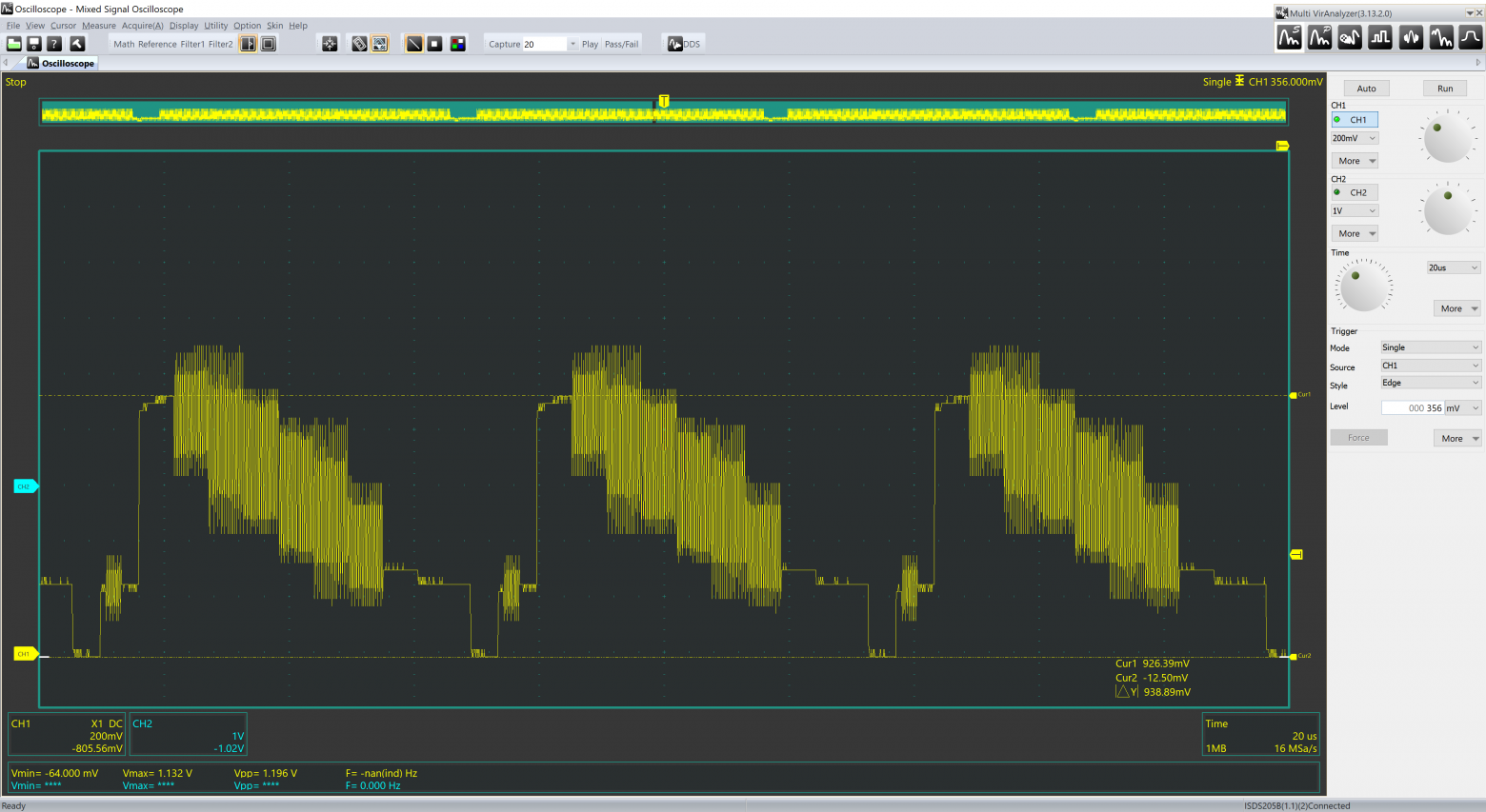
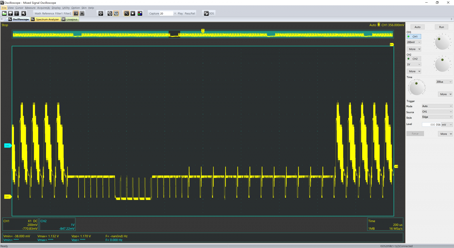
- USB oscilloscope (Intrustar ISDS205B)
- USB video capture card
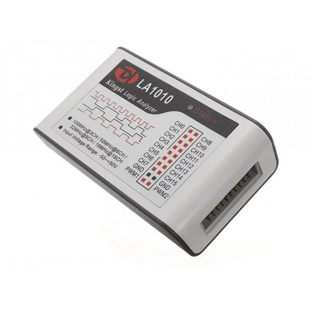
- Kingst LA1010 logic analyzer
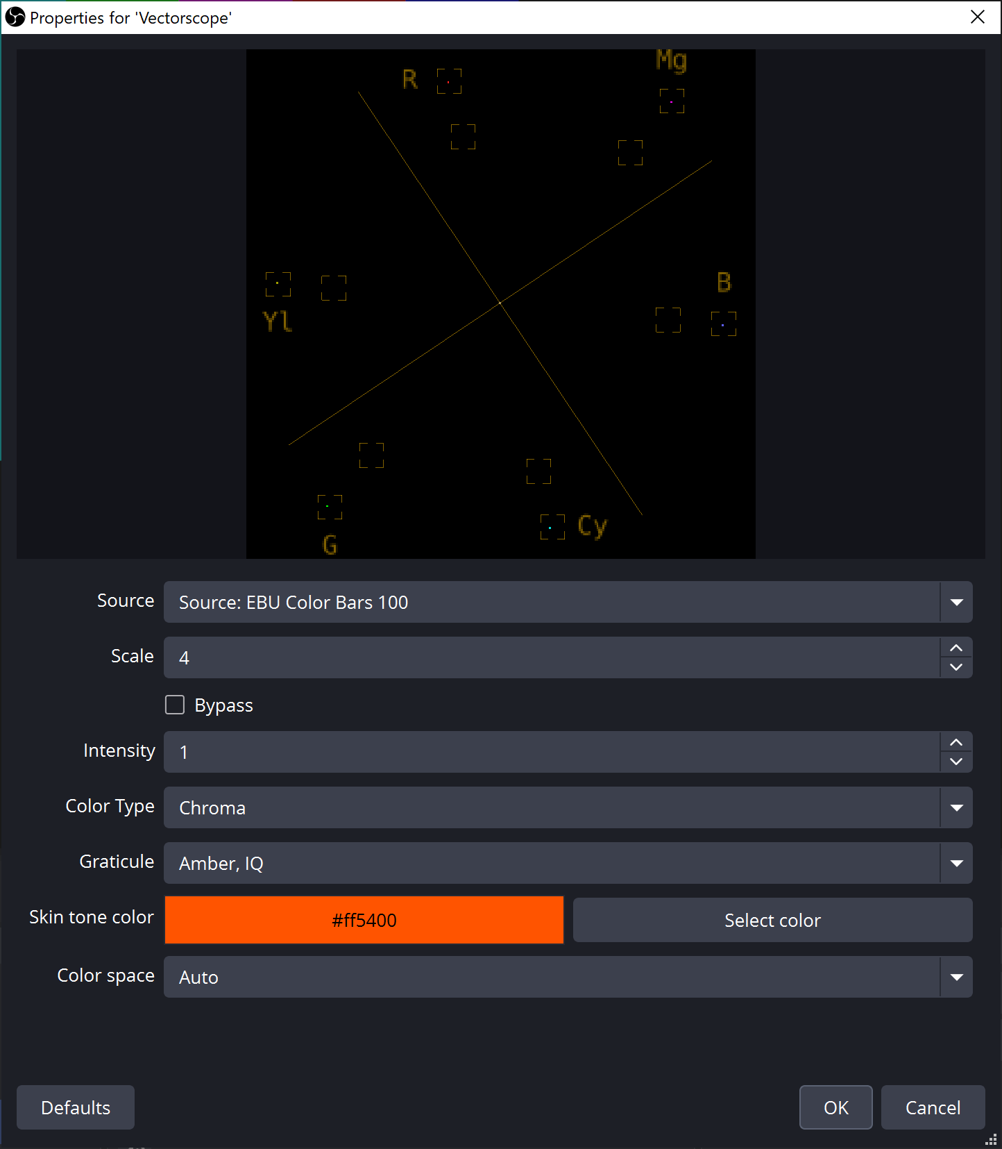
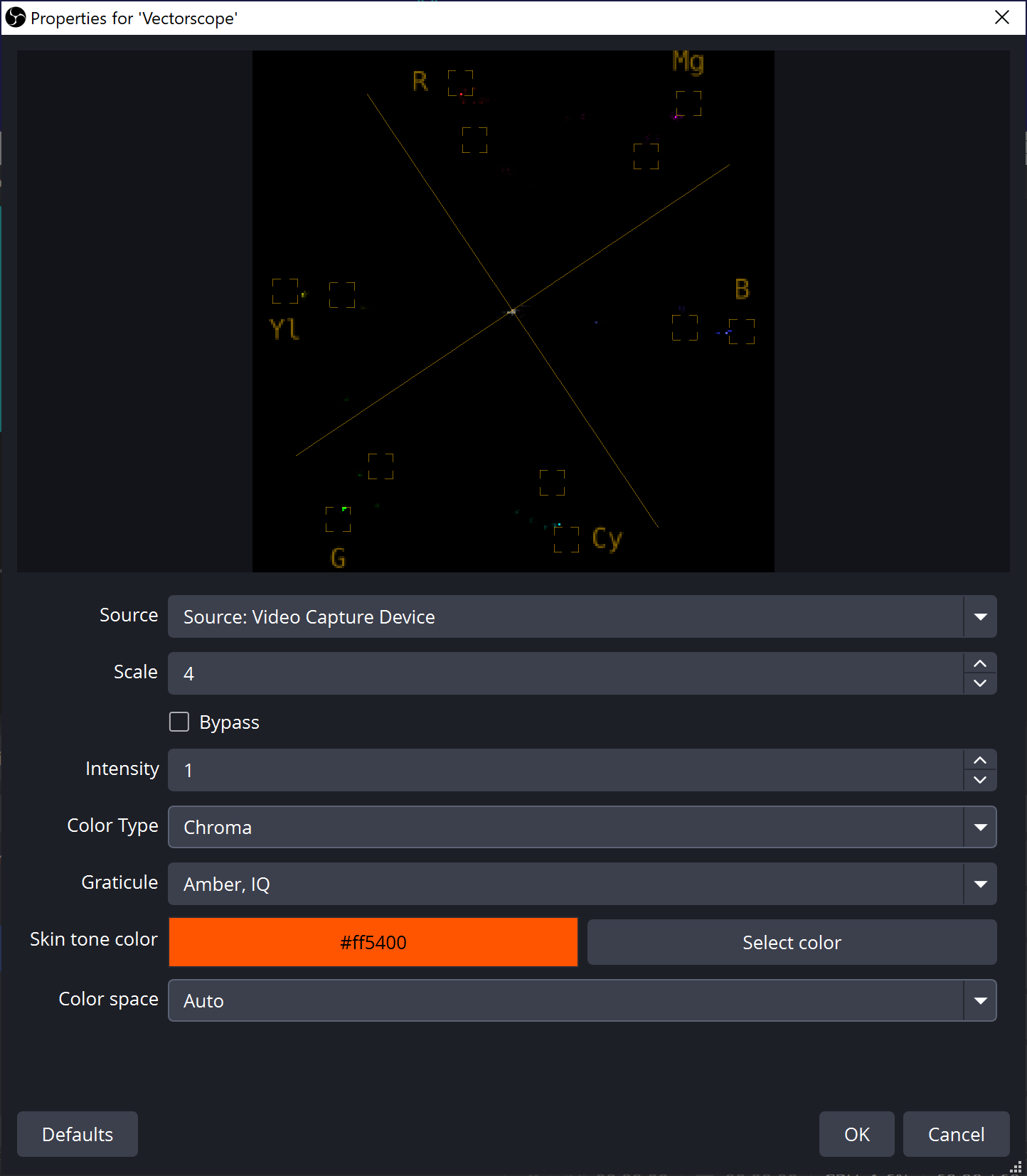
- OBS Studio Vectorscope plugin for color verification
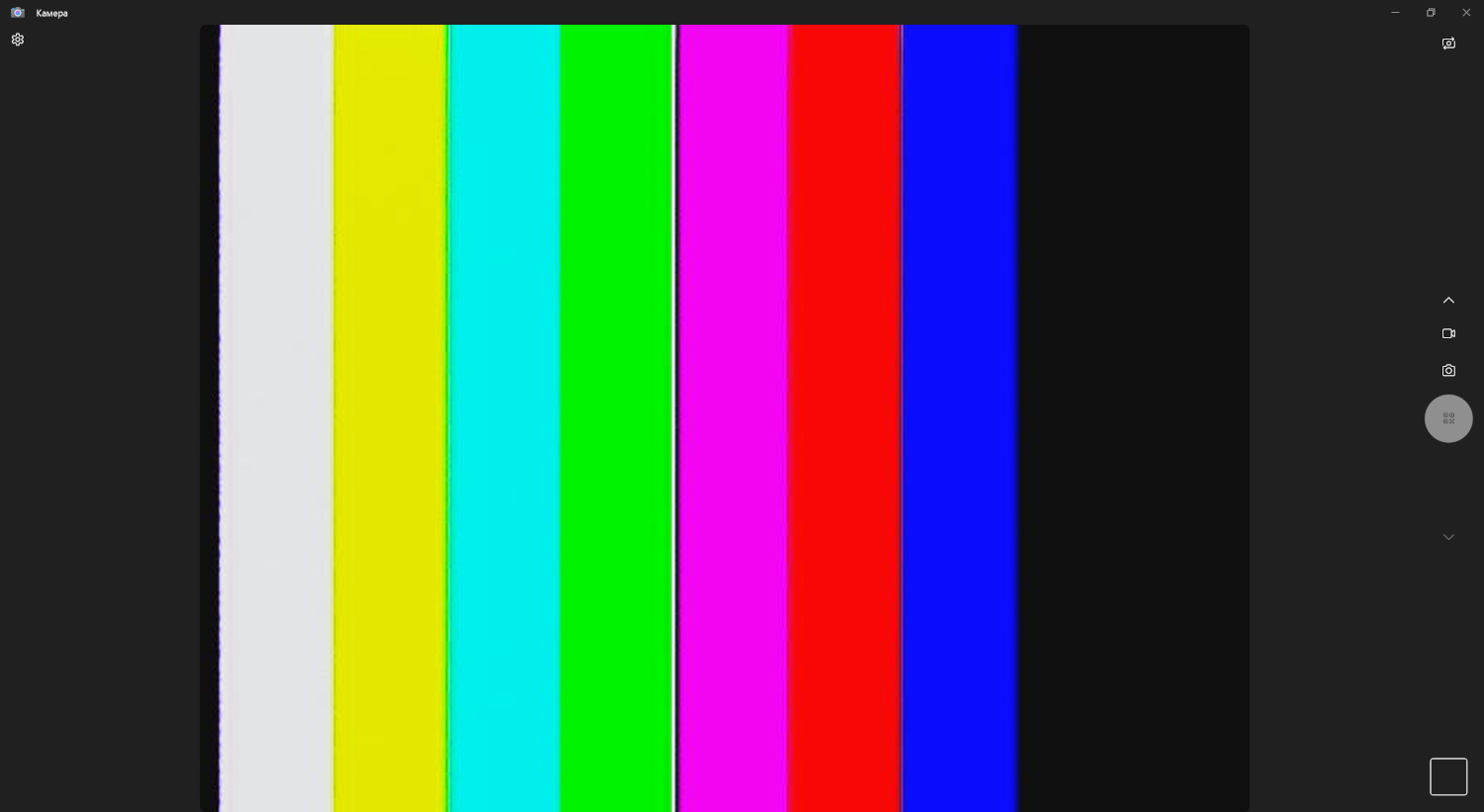
Results
Generated images displayed correctly on television receivers, video capture cards, and test equipment vectorscopes. Oscillogram measurements confirmed approximately 940 mV peak-to-peak amplitude (close to the 1V specification). Vectorscope analysis showed acceptable color accuracy despite discretization effects.
Conclusion
Despite NTSC's obsolescence, understanding composite signal generation teaches fundamental concepts applicable to modern digital imaging and demonstrates practical microcontroller capabilities beyond simple applications. The project shows that with just an R2R DAC and a $4 Raspberry Pi Pico, you can generate a fully standards-compliant color video signal -- a feat that once required expensive dedicated hardware.


