Small-Batch Electric Motor Manufacturing Technology
A practical guide to small-batch manufacturing of brushless electric motors, covering stator construction, winding techniques, rotor assembly with permanent magnets, and carbon fiber reinforcement for high-speed applications.
In this article, I want to share practical technologies for small-batch manufacturing of brushless electric motors. We'll cover the complete process from stator construction through rotor assembly, including all the tooling, materials, and processes involved.
Choosing the Motor Design
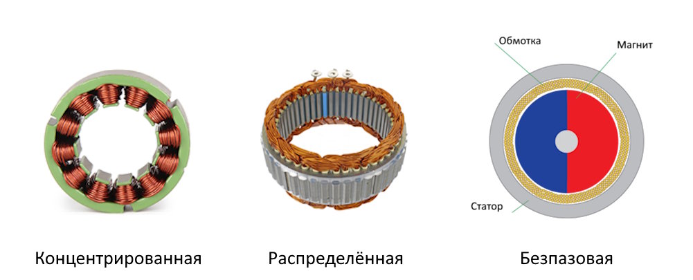
For small-batch production, permanent magnet motors are recommended over asynchronous designs due to their lower manufacturing complexity. Three winding configurations exist:
- Concentrated winding — suits motors up to 100-150 mm in stator diameter/length
- Distributed winding — works better for larger sizes
- Slotless winding — for specialized applications
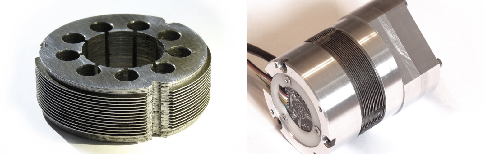
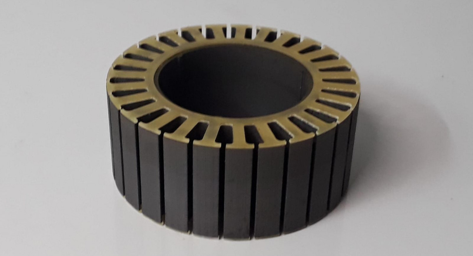
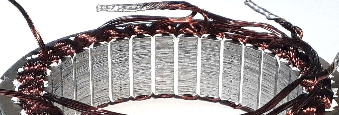
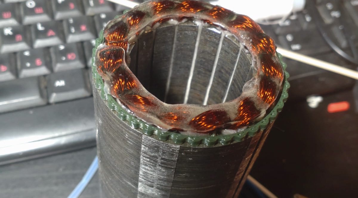
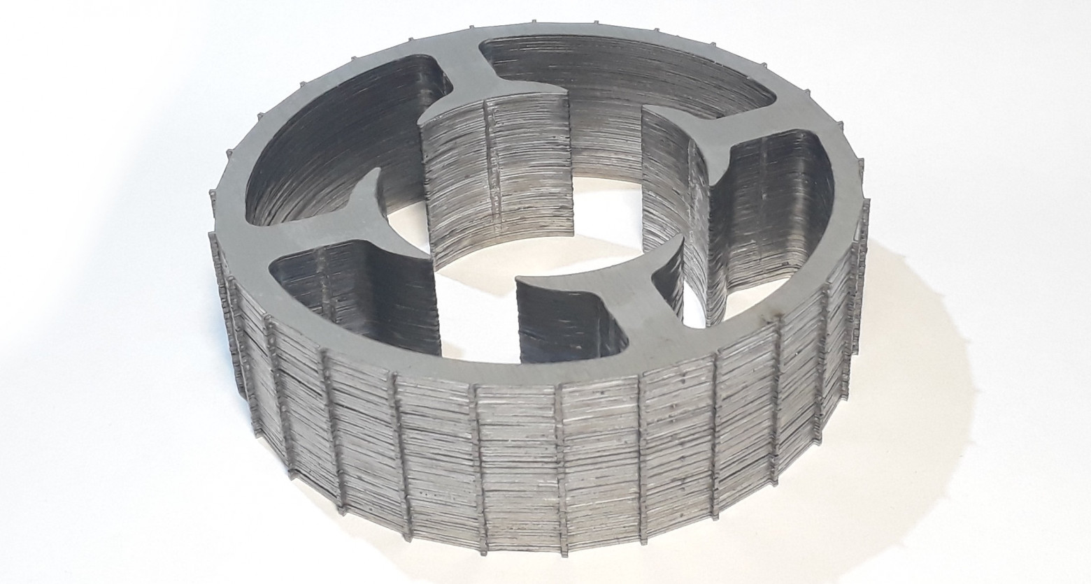
Stator Construction
Steel Selection
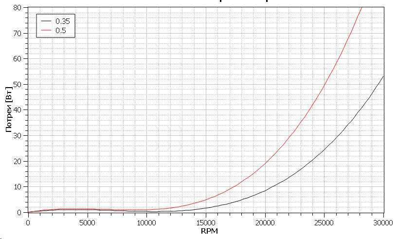
The stator core is built from electrical steel laminations. Recommended grades are 2212 and 2412, with thickness ranging from 0.18 to 0.5 mm. Lamination is essential because it reduces eddy current losses.
The key formula is: ERPM = RPM × PP (where PP is the number of pole pairs). A thickness of 0.35 mm reduces losses by half compared to 0.5 mm steel.
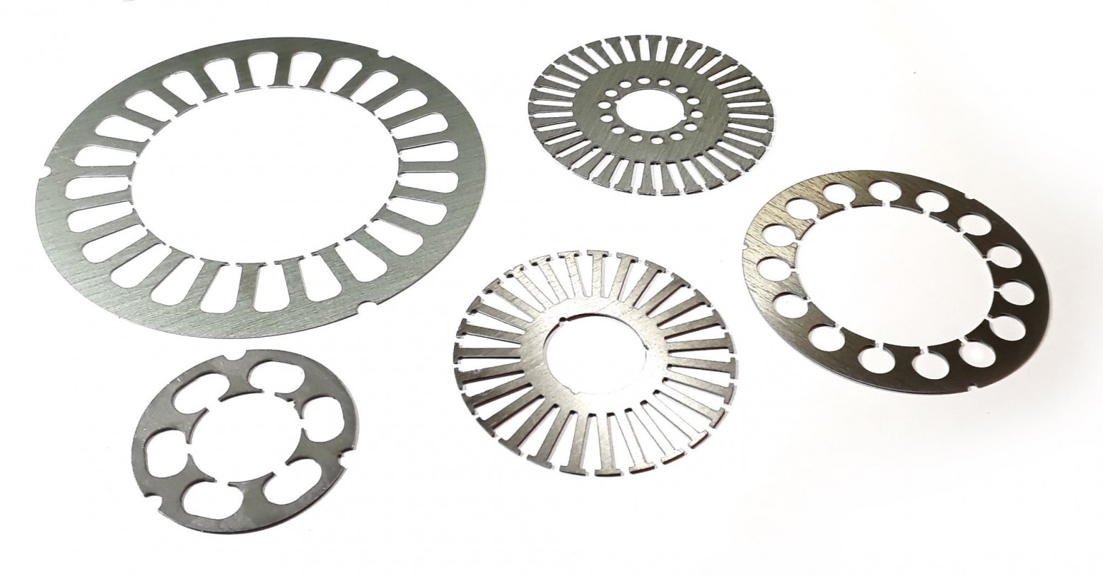
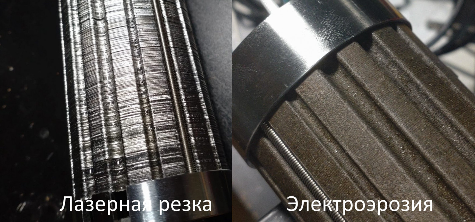
Manufacturing Methods
Two primary methods exist for cutting stator laminations:
- Laser cutting — the most economical approach. Tolerates air gaps of 0.75-1 mm. Suitable for larger stators with diameters of 40 mm and above.
- Electrical Discharge Machining (EDM) — approximately ten times more expensive but enables much higher precision. Achieves air gaps as small as 0.5 mm. Ideal for small diameter stators under 40 mm.
Insulation Materials
Proper insulation between the winding and stator core is critical. The main options are:
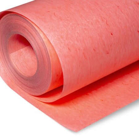
- Synthofleks — durable, damage-resistant, and compatible with epoxy impregnation. The best all-around choice.
- Paper/Electrical cardboard — thermally stable but requires multiple layers for adequate protection.
- Glass-fiber laminates — used as protective overlays on top of completed windings.
The Winding Process
Wire specifications for motor windings:
- Copper diameter: 0.4-0.6 mm
- Litz wire is recommended for larger cross-sections to reduce skin effect
- Insulation types: PETV-2 (up to 150°C), PET-155 (up to 155°C), PET-200-2 (up to 200°C)
Manual winding is performed using two methods: concentrated (per-tooth) winding and distributed (slot insertion) winding. Manual winding requires practice — experienced operators achieve tighter packing and easier coil placement.
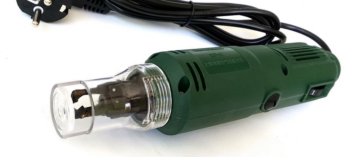
Wire Stripping Techniques
Removing insulation from magnet wire requires care to avoid damaging the conductor:
- Electric strippers — risk breakage on thin wires
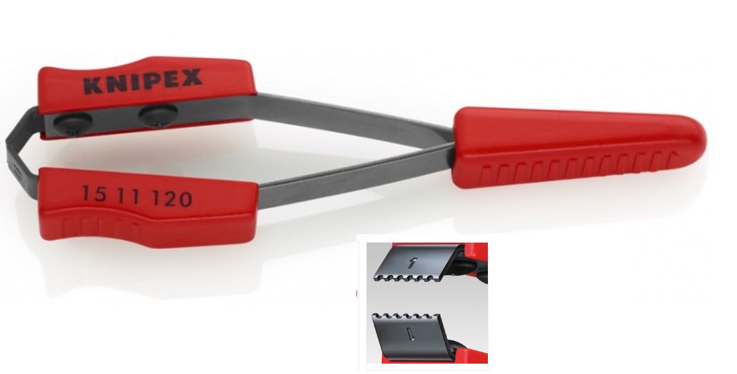
- Pliers — safe for bundles up to 10 strands
- Knife scraping — effective for larger bundles; pre-burning the insulation with a lighter facilitates removal
Important: Never solder winding wire directly as lead-out connections. The wire is too fragile. Instead, use fluoropolymer or silicone-jacketed leads for external connections.
Potting and Impregnation
Impregnation protects windings from moisture, vibration, and electrical failure:
- For stators up to 30 mm thick: Epoxy resin applied via syringe at 50-60°C preheating temperature
- For longer stators: Polyester compound KP-55-1, applied through immersion or syringe. Followed by oven heating. The process must be repeated 2-3 times for optimal penetration.
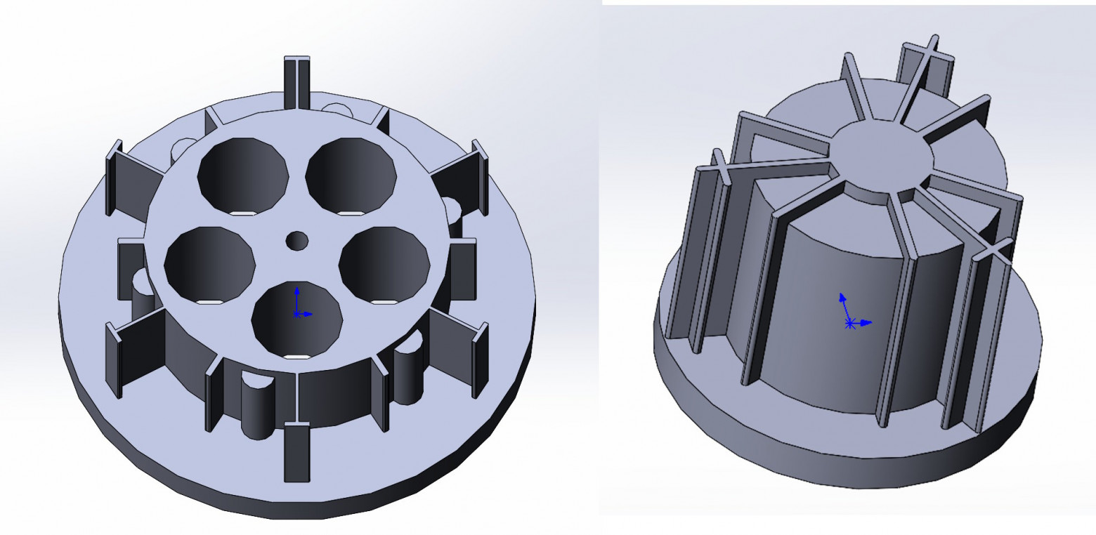
Rotor Design and Assembly
The rotor shaft is made from magnetic steel (for example, 30KhGSA hardened to 40 HRC). Hardening is essential to prevent damage during assembly.
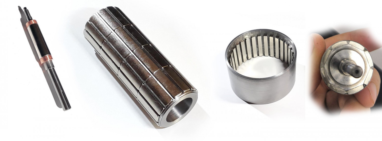
Magnet Selection and Mounting
Two main magnet types are used:
- Neodymium (NdFeB) — for temperatures up to 200°C
- Samarium-cobalt — for higher temperature applications
Mounting configurations include:
- Single ring magnet for high-speed motors (above 3000 RPM)
- Multiple segments for multi-pole rotors, with spacing between segments
- EDM-cut custom geometries for specialized applications
Recommended adhesives for magnet bonding:
- LOCTITE EA 9497
- Polyxipol (civilian equivalent)
- Kafuter (Chinese brand with good results)
Surface preparation is critical: roughen the surface, create grooves, and degrease thoroughly before bonding.
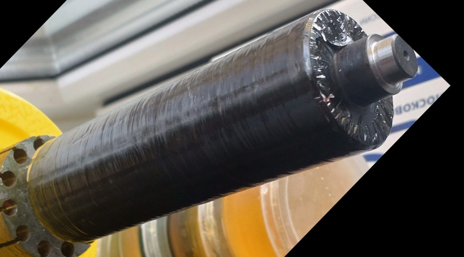
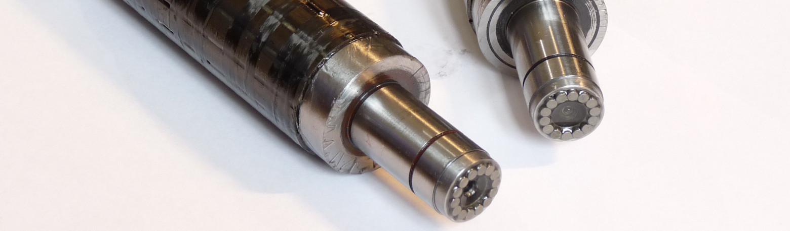
Carbon Fiber Rotor Reinforcement
For inner-runner motors operating at high speeds, carbon fiber winding prevents magnet detachment:
- Coat the rotor with epoxy resin
- Wind carbon fiber evenly without twists
- Impregnate with additional resin
- Wrap with non-stick film and tape
- The result is a smooth, durable carbon layer that requires no additional machining
Hall Effect Sensor Placement
The optimal placement for Hall sensors is directly in the stator slots. An alternative approach uses a false rotor on the shaft end with PCB-mounted sensors, which requires angular adjustment capability for fine-tuning.
FAQ
What is this article about in one sentence?
This article explains the core idea in practical terms and focuses on what you can apply in real work.
Who is this article for?
It is written for engineers, technical leaders, and curious readers who want a clear, implementation-focused explanation.
What should I read next?
Use the related articles below to continue with closely connected topics and concrete examples.