Project Caretaker: A Remotely Controlled Robot on ESP32-CAM
A detailed build log of a DIY tracked robot called 'Caretaker' featuring an ESP32-CAM, AI-assisted design with 1500+ generated images, custom 3D-printed chassis, SLA-printed housing, and Home Assistant integration for remote control and video streaming.
Introduction
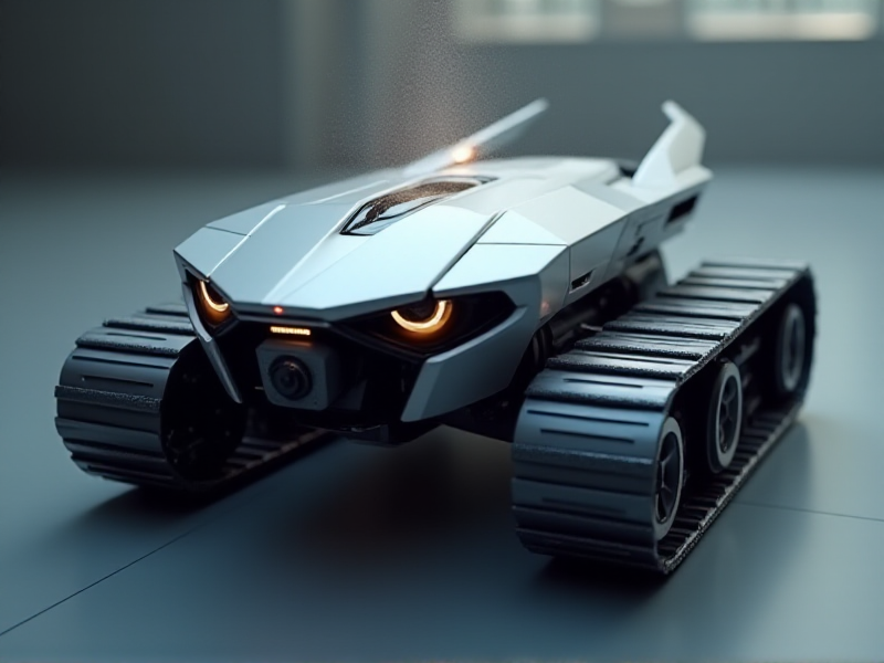
This article documents the complete three-month development of "Caretaker" (Смотритель), a DIY tracked robot featuring AI-assisted design, custom 3D-printed components, and Home Assistant integration. The project brings together electronics, 3D printing, embedded programming, and smart home technologies into a single coherent system.
Core Features
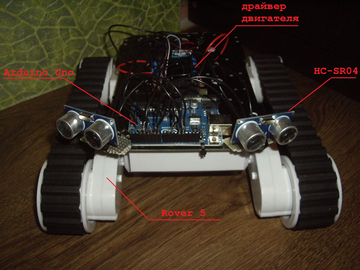
- ESP32-CAM microcontroller with WiFi and Bluetooth control
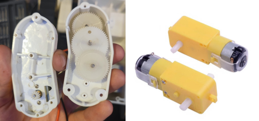
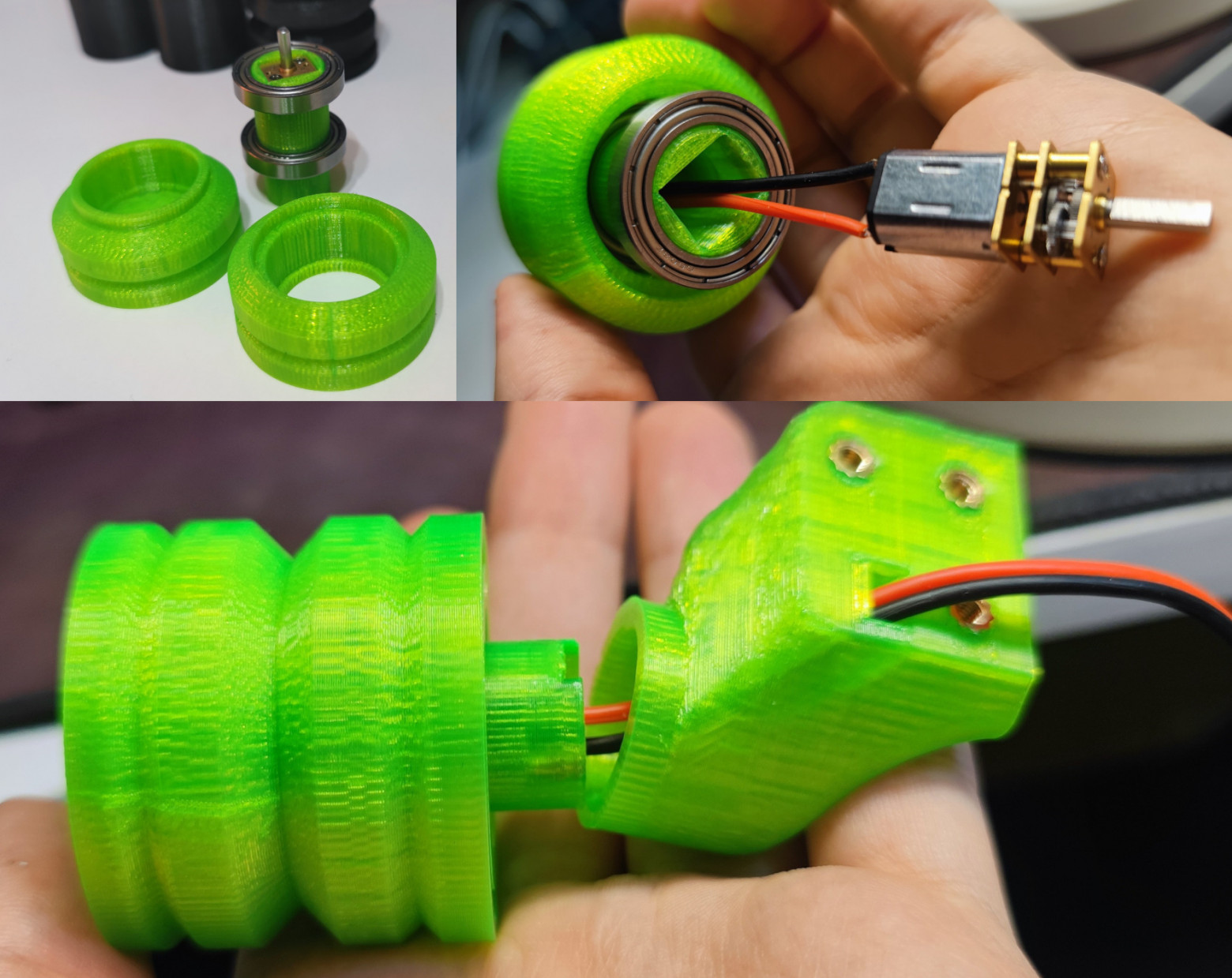
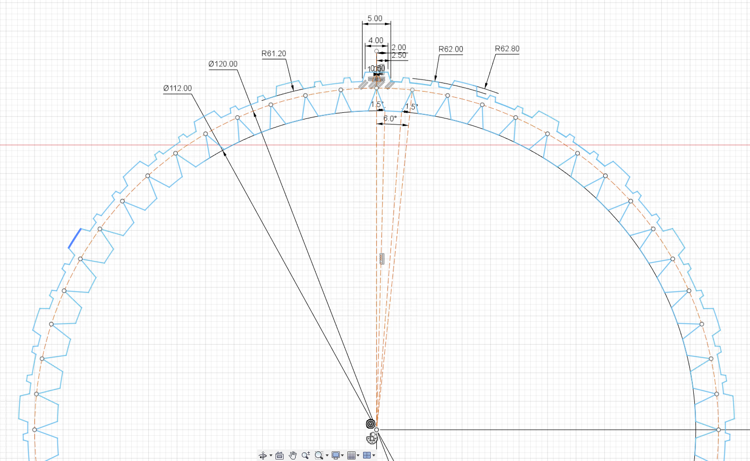
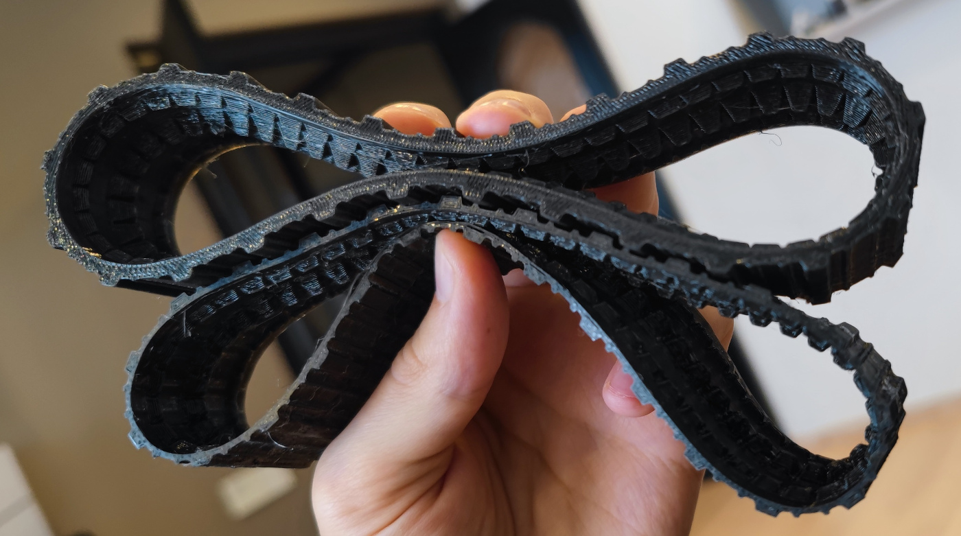
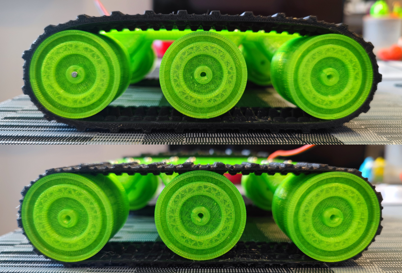
- Custom dual-motor tracked chassis with 3D-printed wheels and TPU track segments
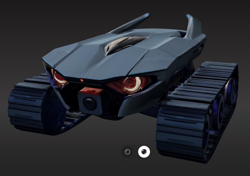
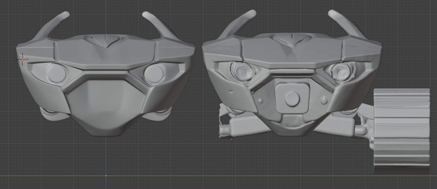
- SLA-printed polycarbonate housing derived from AI-generated designs
- Charging dock with spring-loaded contact system
- Dual control modes: joystick and slider interfaces
- MJPEG video streaming with quality adjustment
Hardware Specifications
- 3S LiPo battery (12.6V nominal)
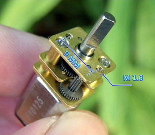
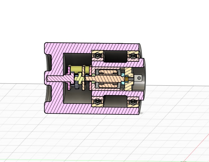
- GA12-N20 motors with metal gearboxes (150:1 ratio)
- L293D motor driver
- Custom PCB fabricated using photopolymer printing technique
- RGB LED indicators in eye sockets
AI-Assisted Design Process
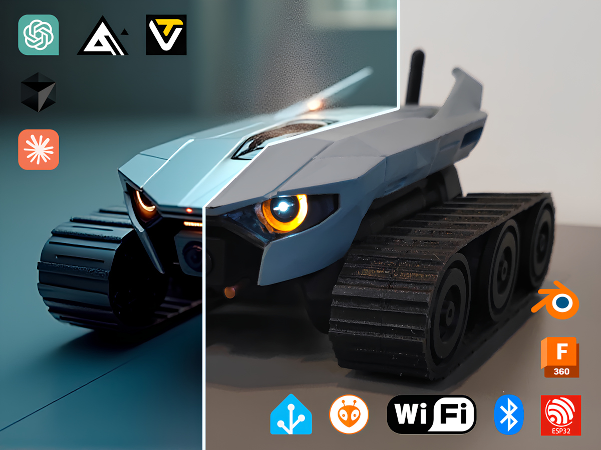
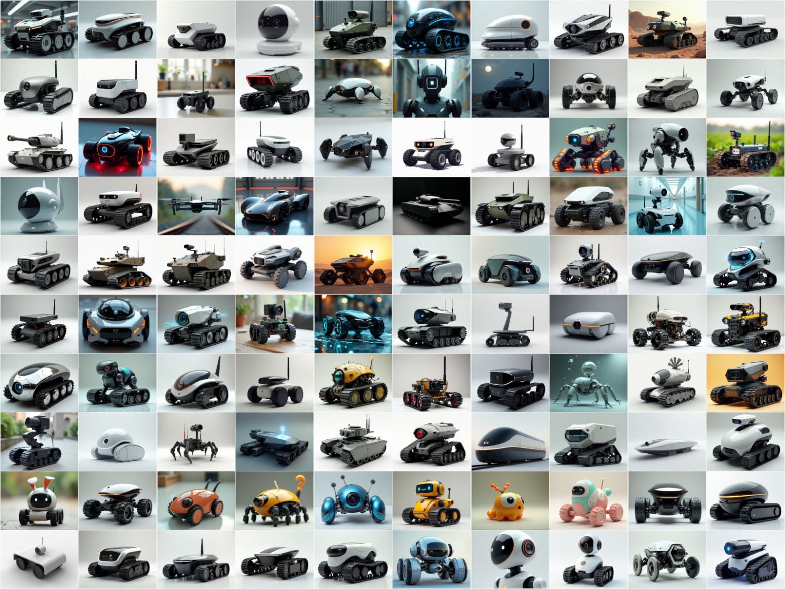
The author employed generative AI extensively during the design phase. GPT-4o generated varied prompts based on requirements, while a locally deployed Stable Diffusion Forge with FLUX.1 model produced over 1,500 images across 150 prompts. This massive image generation effort helped conceptualize the robot's appearance before committing to a final design.
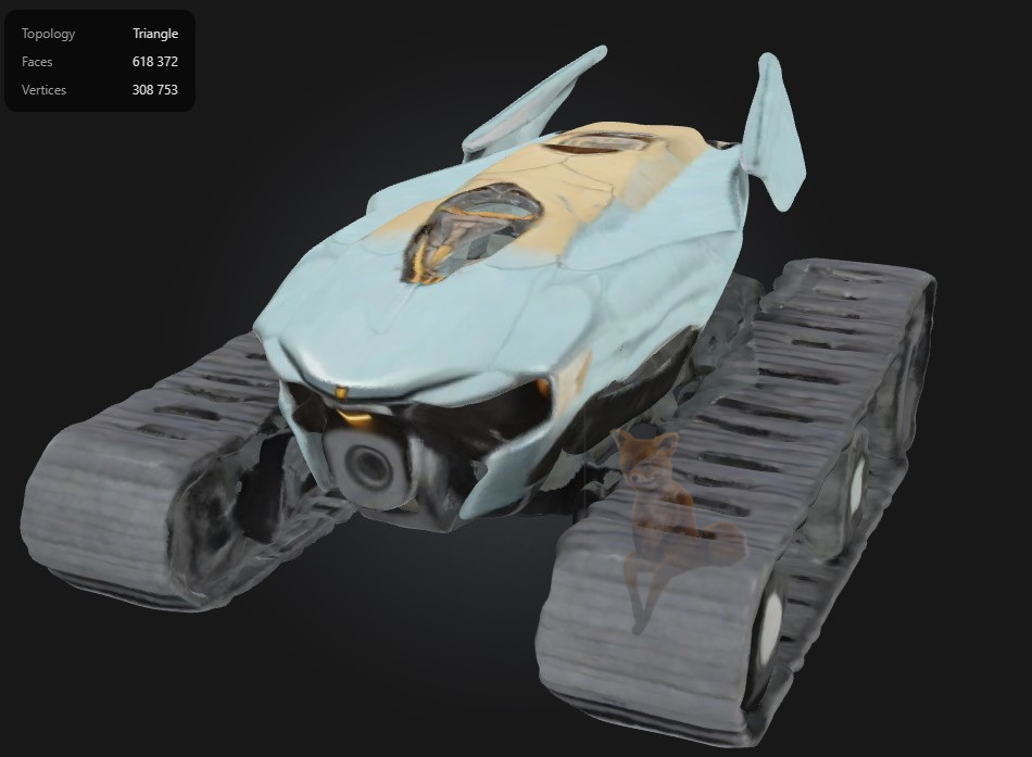
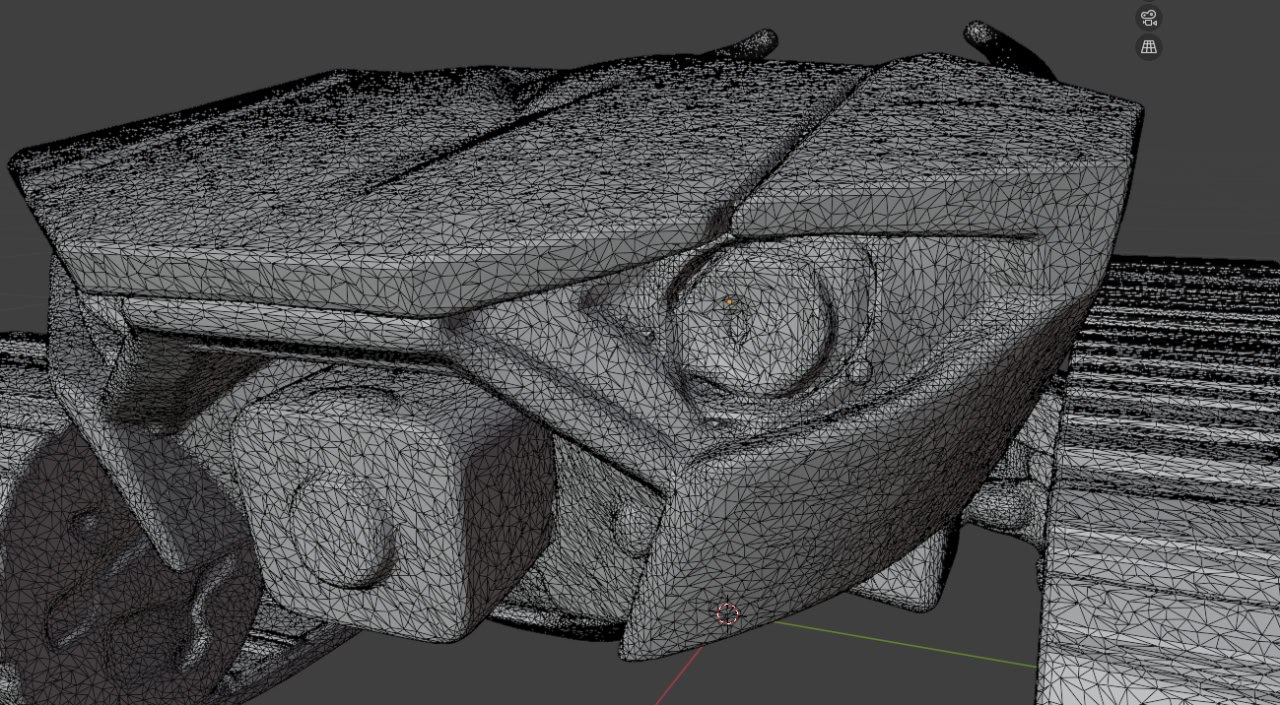
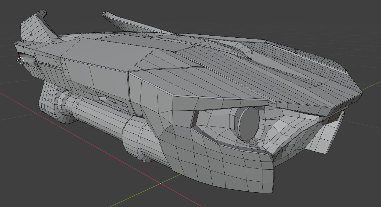
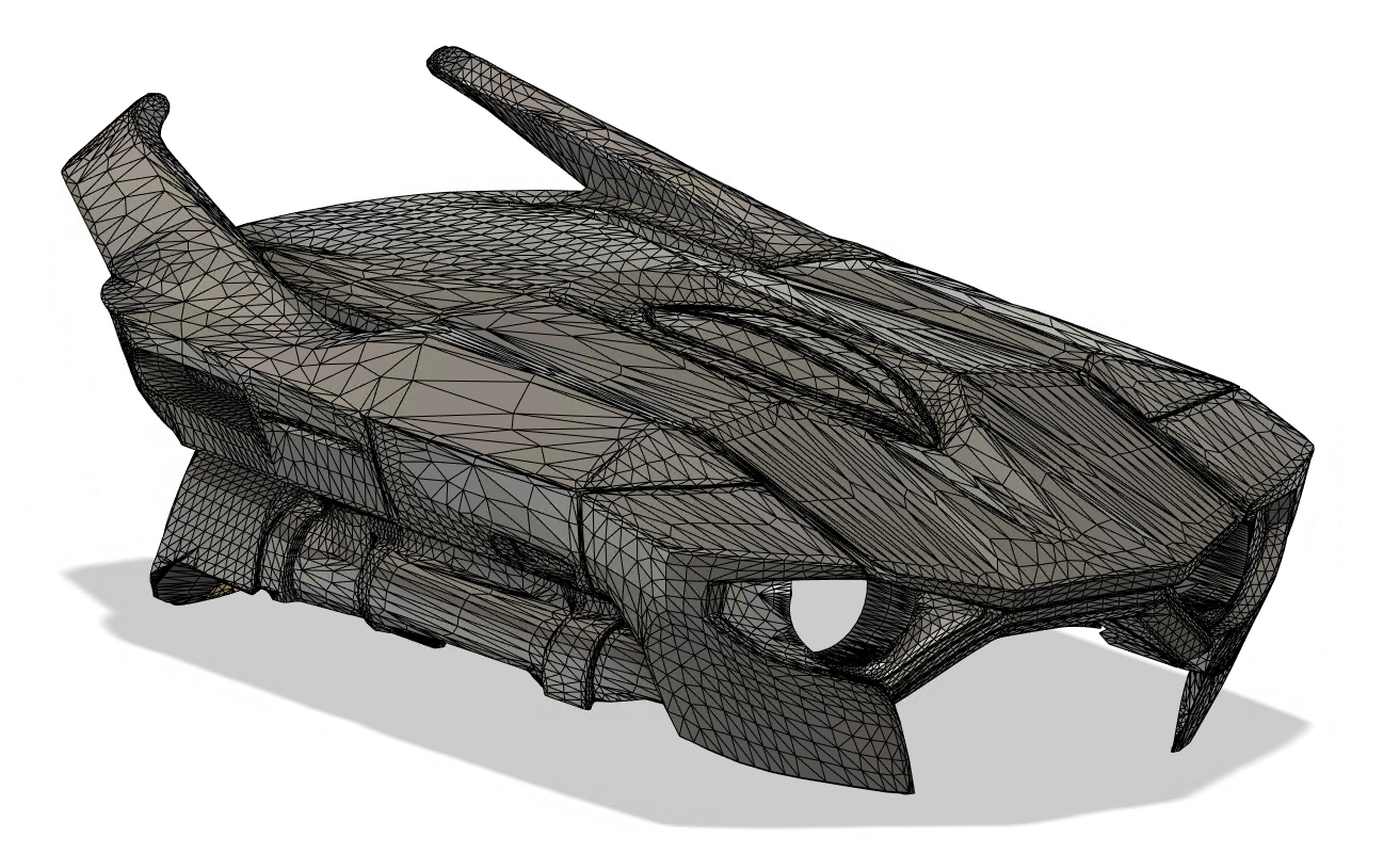
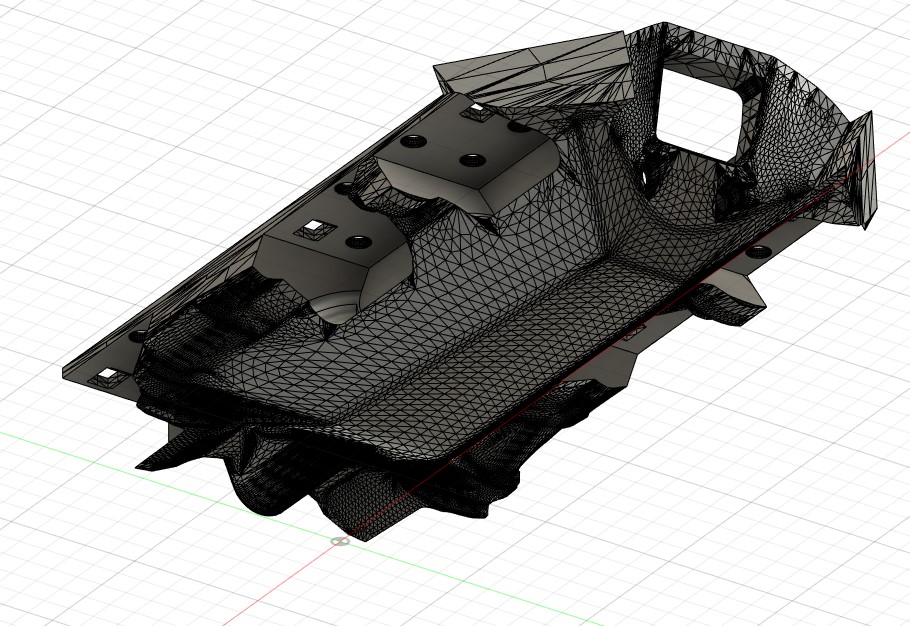
The design evolution followed a pipeline: AI image generation for conceptualization, 3D model generation via Tripo3D, manual retopology in Blender, and final CAD refinement using Fusion 360.
Manufacturing Innovations
PCB Production
The developer created an svg2stl utility (written with Claude Sonnet 3.7 in Cursor) to directly print circuit layouts on photopolymer printers, completely eliminating the traditional film-based PCB manufacturing process. This innovative approach leverages the high resolution of SLA printers for circuit board fabrication.
Housing
Initial FDM prototypes proved inadequate in terms of surface quality. The switch to SLA printing using ABS-Like Resin Pro 2 yielded superior surface finish with minimal shrinkage — contrary to the author's initial assumptions about resin-based printing.
Track Design
The tracks went through several iterations. The final 1.2mm TPU material (versus initial 3mm) balanced flexibility with motor compatibility. However, grip on vertical surfaces proved suboptimal — vertical wall climbing was impossible despite adequate motor torque.
Software Architecture
The firmware implements FreeRTOS task distribution across ESP32's dual cores:
- Bluetooth gamepad handling
- MJPEG streaming
- HTTP command interface
- Motor control
- Telemetry logging
The web UI is compiled into C arrays with gzip compression, avoiding SPIFFS storage overhead entirely. This approach provides faster access times and more reliable operation.
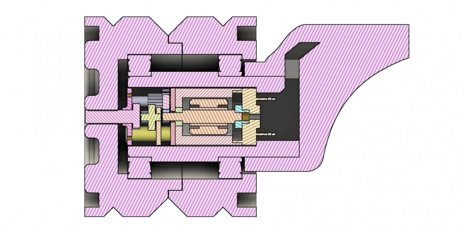
Charging Dock
The robot features a custom-designed charging dock with spring-loaded contacts. The dock allows the robot to autonomously connect for charging, making the system more practical for long-term deployment.
Home Assistant Integration
The integration went through two phases. The initial iframe-based proxy approach was rejected due to security concerns with mixed content and authentication. The final solution uses Home Assistant's native signed-path authentication mechanism for secure streaming video access, providing a much cleaner integration.
Notable Technical Challenges
The author identified a critical hardware constraint: the ESP32's ADC2 controller is engaged when WiFi is active, preventing battery voltage monitoring via analog input. This is a well-known ESP32 limitation that required a workaround.
Track grip limitations also emerged during testing. Despite adequate motor torque, the robot could not climb vertical walls. The TPU material simply didn't provide enough friction for that use case.
Assembly and Final Build
Open Source Resources
All project components have been published as open source, including:
- 3D models (STL, F3Z, STP formats)
- KiCad schematics and PCB layouts
- Firmware source code
- Home Assistant custom component
- Design documentation (150+ AI-generated reference images)
Conclusion
This three-month project represents a comprehensive integration of electronics, fabrication, embedded systems, and smart-home technologies within a single coherent system. The extensive use of AI tools — from image generation to code writing — demonstrates how modern developers can leverage these tools to accelerate the prototyping and design process, even for complex physical projects.
FAQ
What is this article about in one sentence?
This article explains the core idea in practical terms and focuses on what you can apply in real work.
Who is this article for?
It is written for engineers, technical leaders, and curious readers who want a clear, implementation-focused explanation.
What should I read next?
Use the related articles below to continue with closely connected topics and concrete examples.