A Phone for 600 Apartments: Turning a Broken Intercom into a GSM Phone
A creative hardware project that converts a broken Cyfral CCD-20 intercom into a fully functional GSM phone using a Raspberry Pico, SIM800L module, and salvaged lithium-ion batteries from disposable vapes.
The Concept
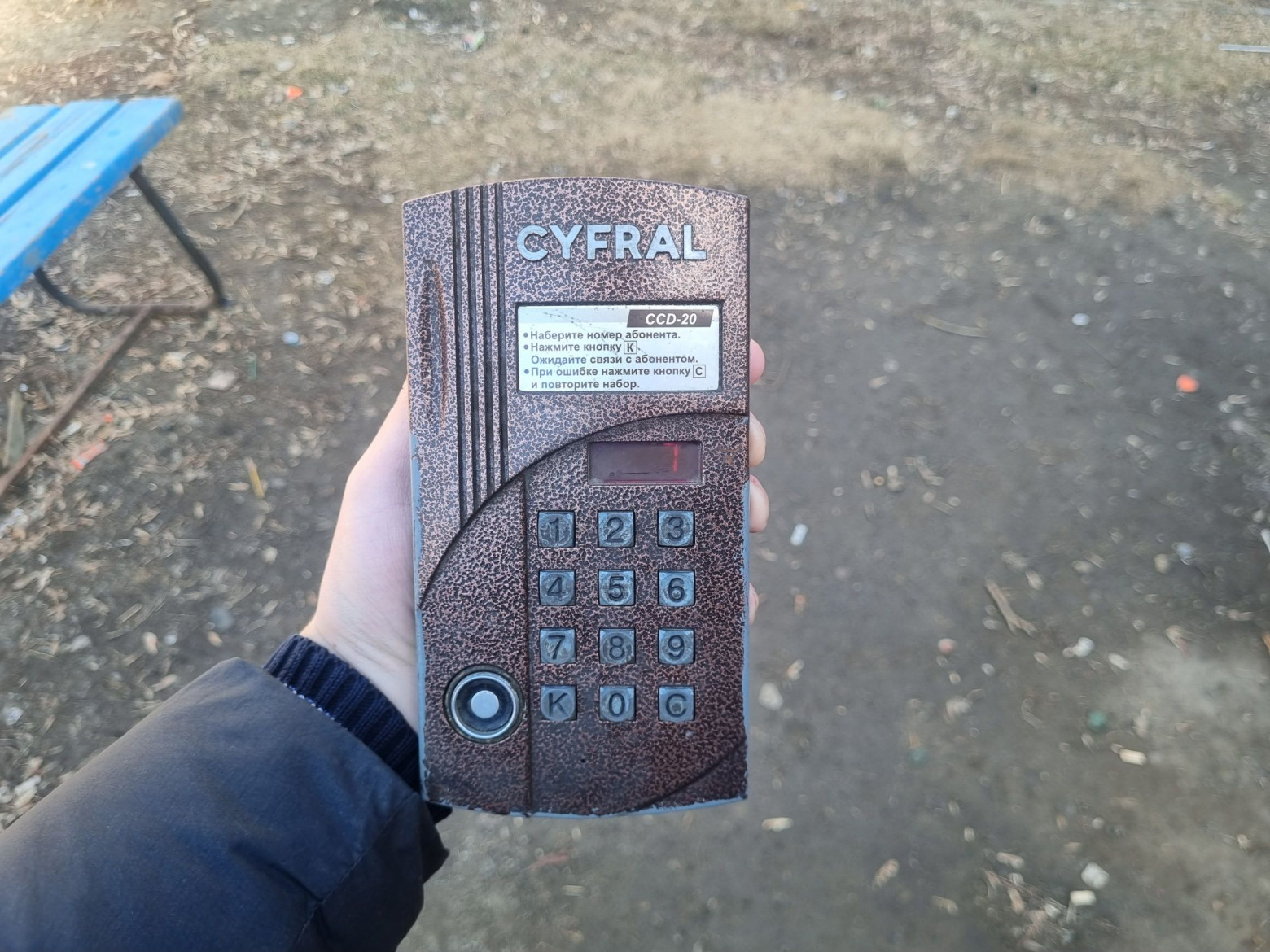
There are plenty of DIY "phone" projects built on microcontrollers out there. I decided to build my device inside an intercom housing, inspired by the internet meme about a "phone for 600 apartments."

Equipment Overview
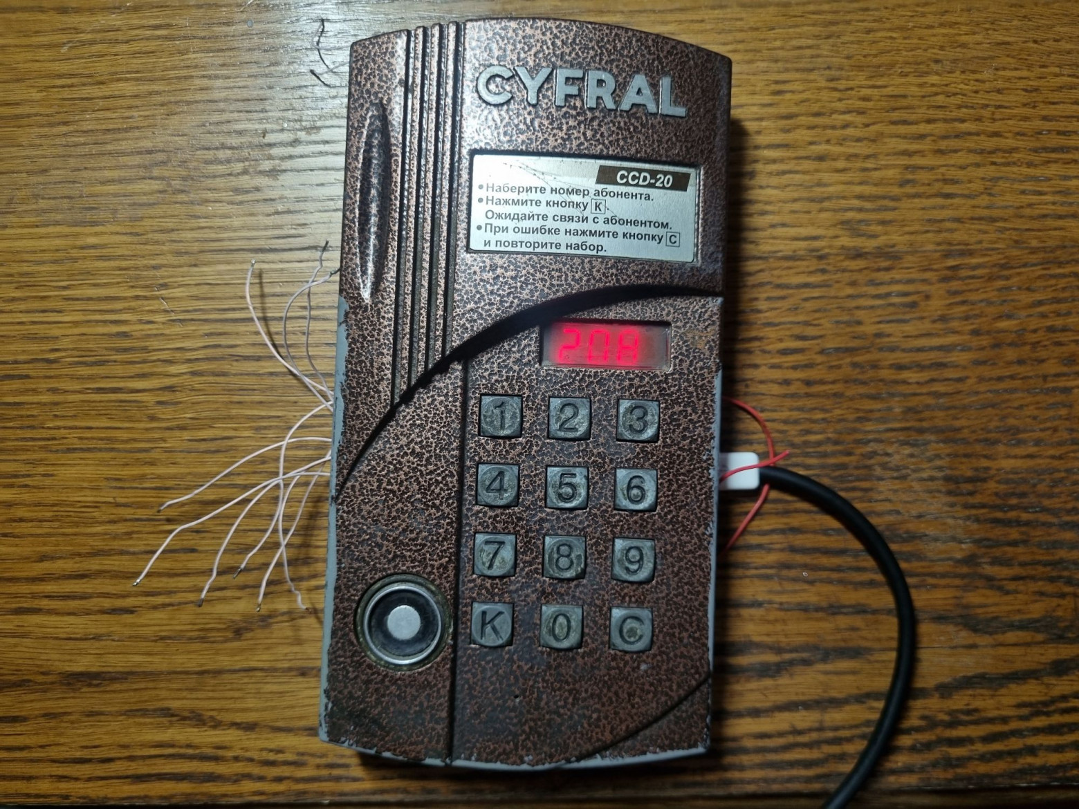
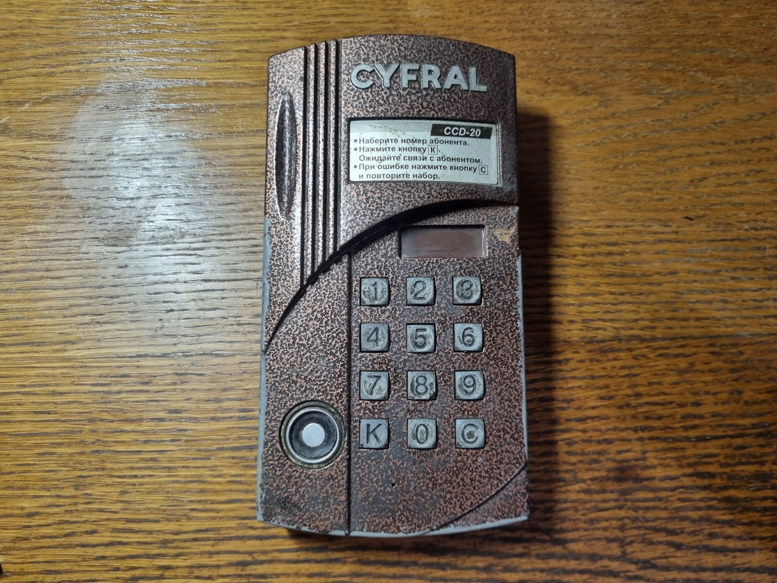
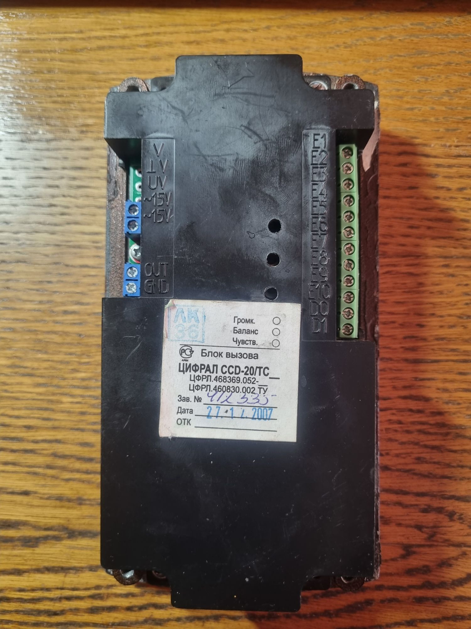
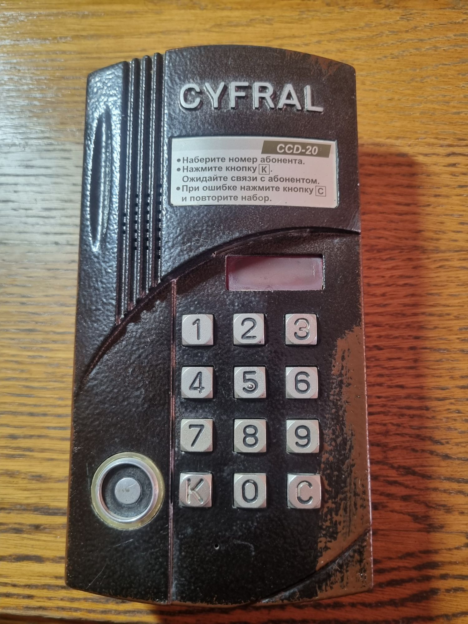
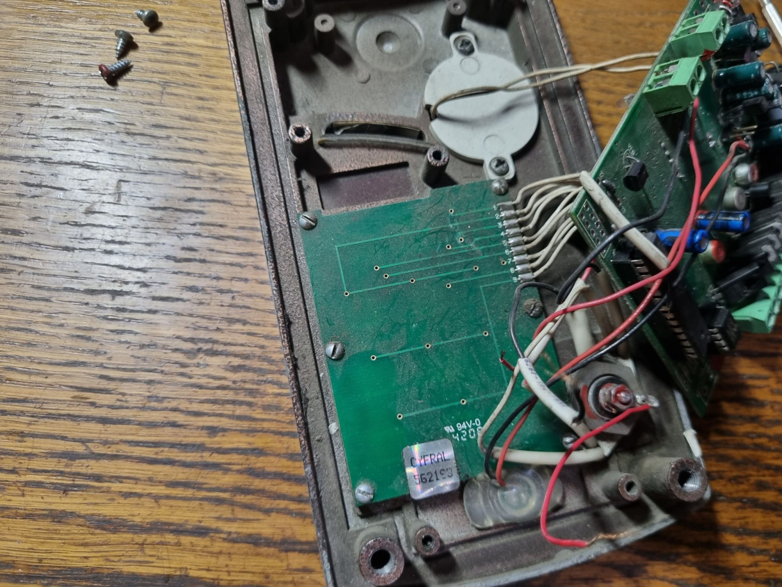
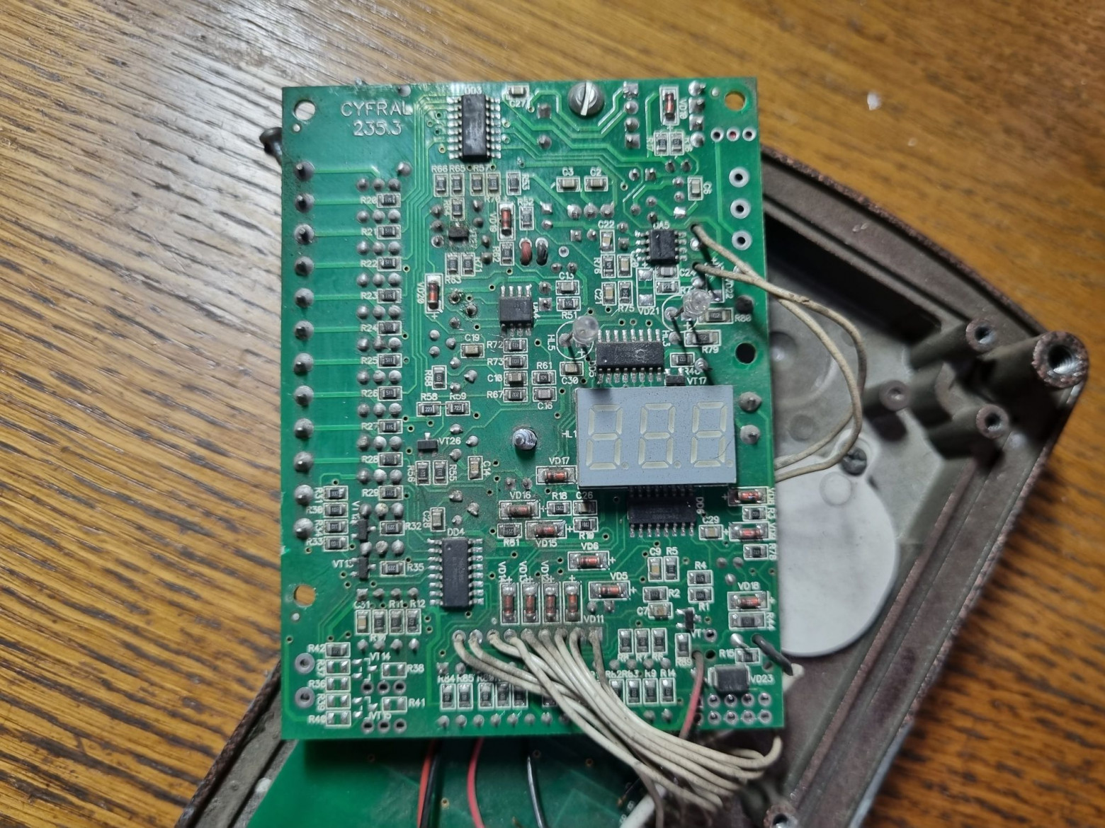
The main component was a broken Cyfral CCD-20 intercom — a coordinate-type intercom with a built-in switching unit for twenty subscribers. Despite the meme name, the actual device supports a maximum of 40 apartments with expansion.
The RFID reader turned out to be broken due to a burned-out microcontroller pin, which made the device a perfect candidate for conversion.
Electronics
The components include:
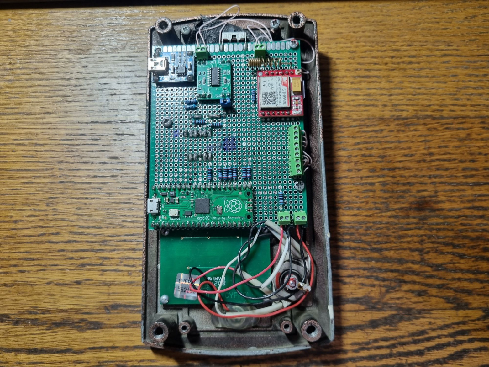
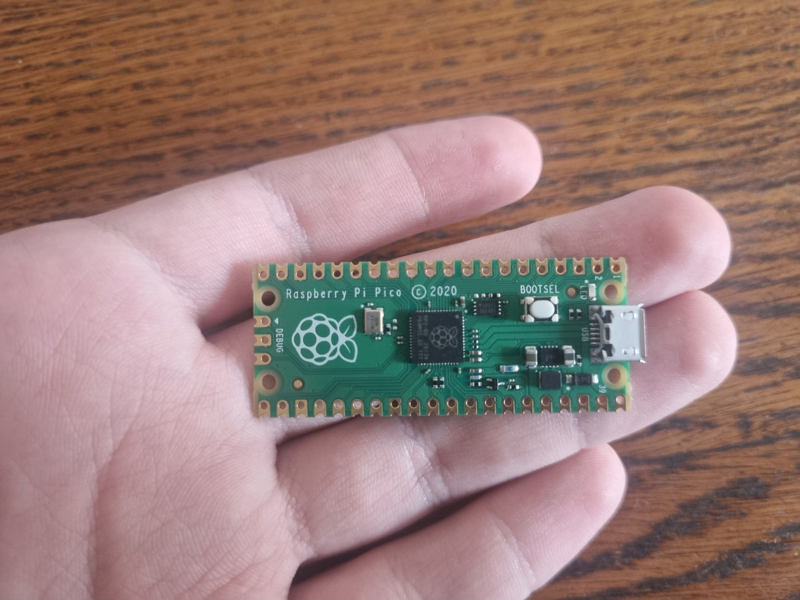
- Raspberry Pico (RP2040) — the main controller
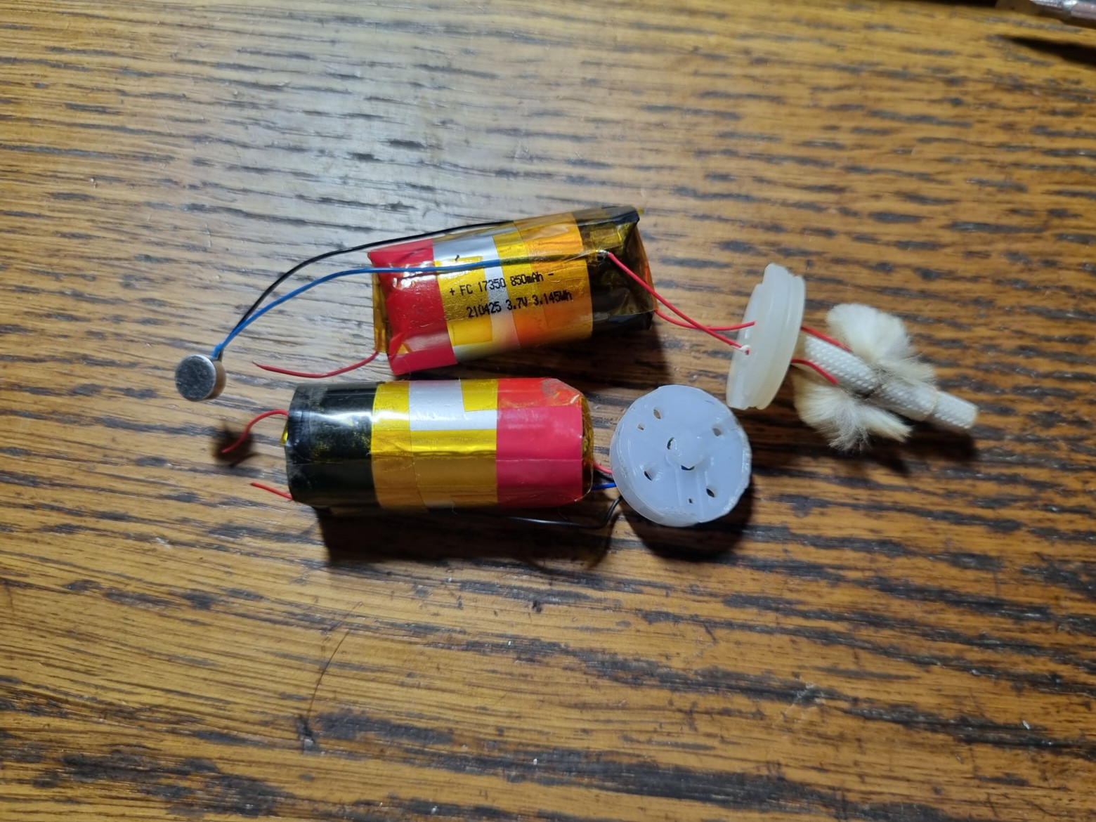
- Lithium-ion batteries from disposable vapes
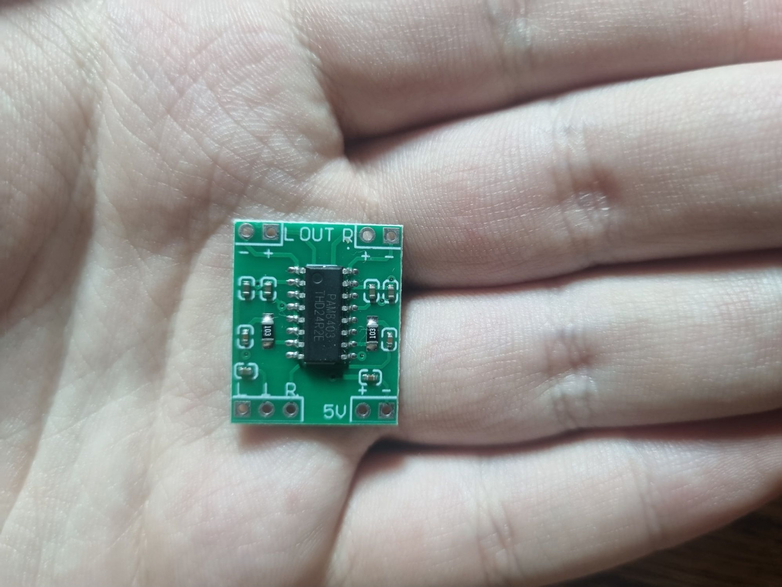
- PAM8403 amplifier for the speaker
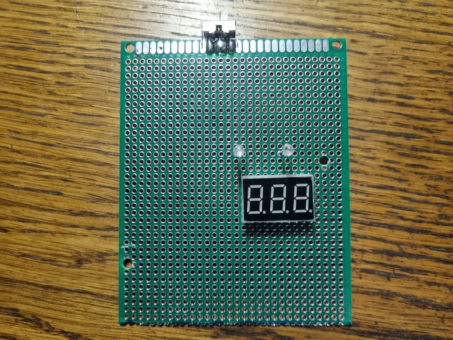
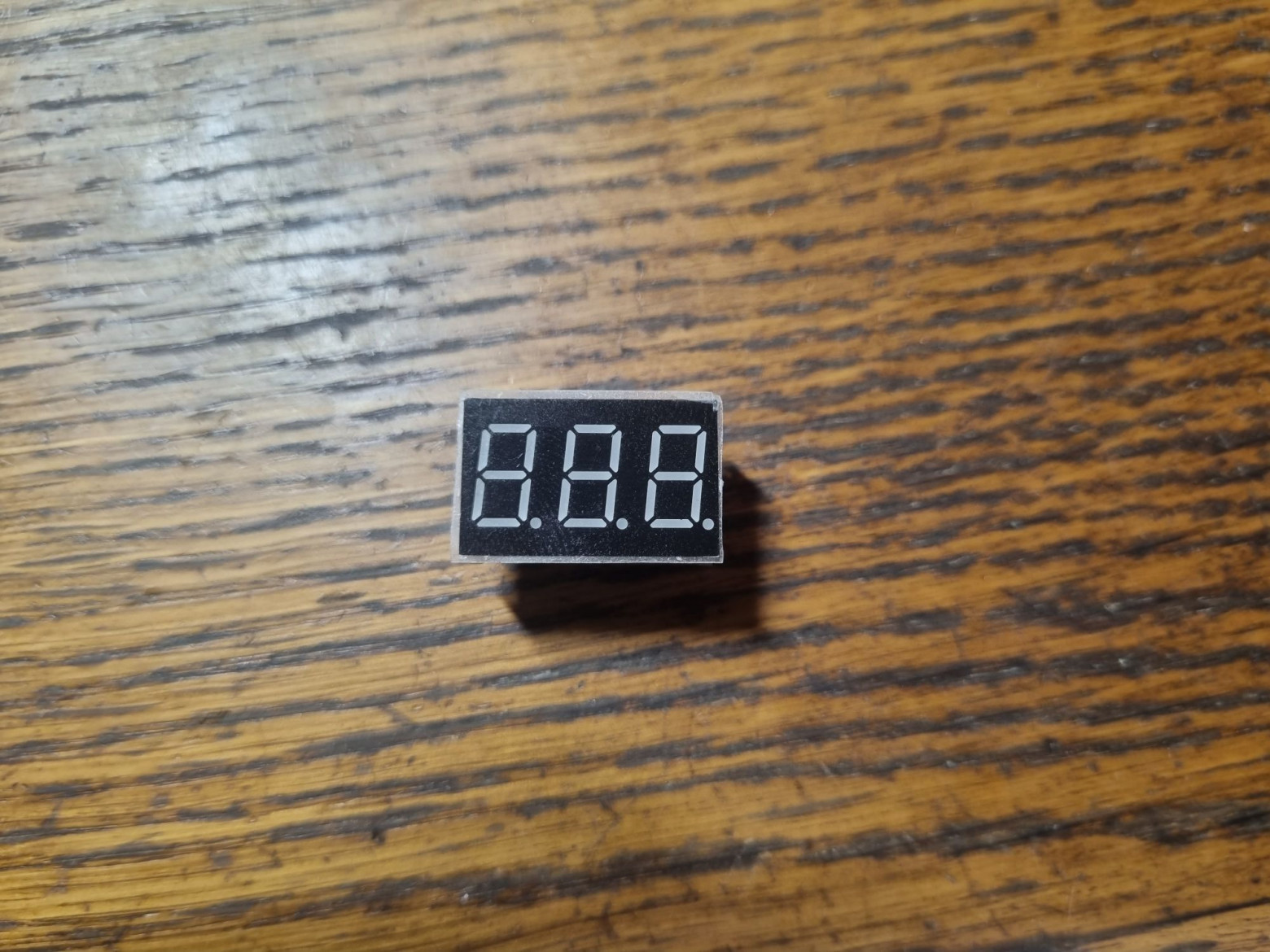
- Seven-segment display KEM-3631AR
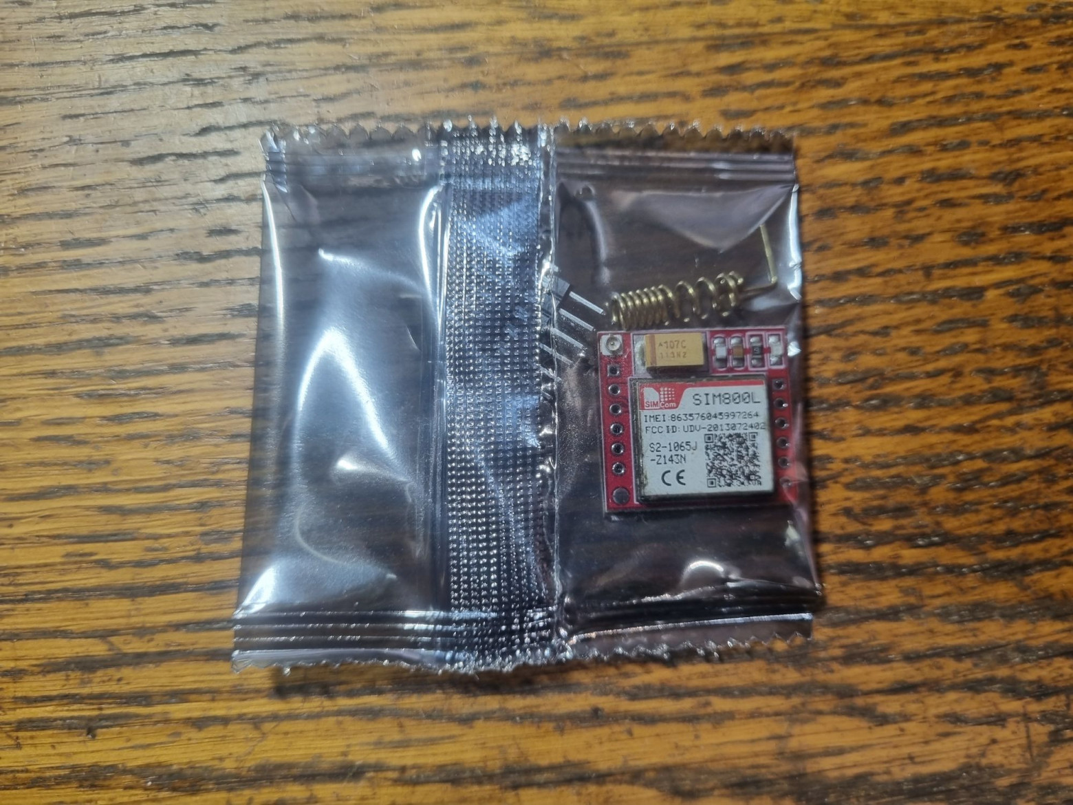
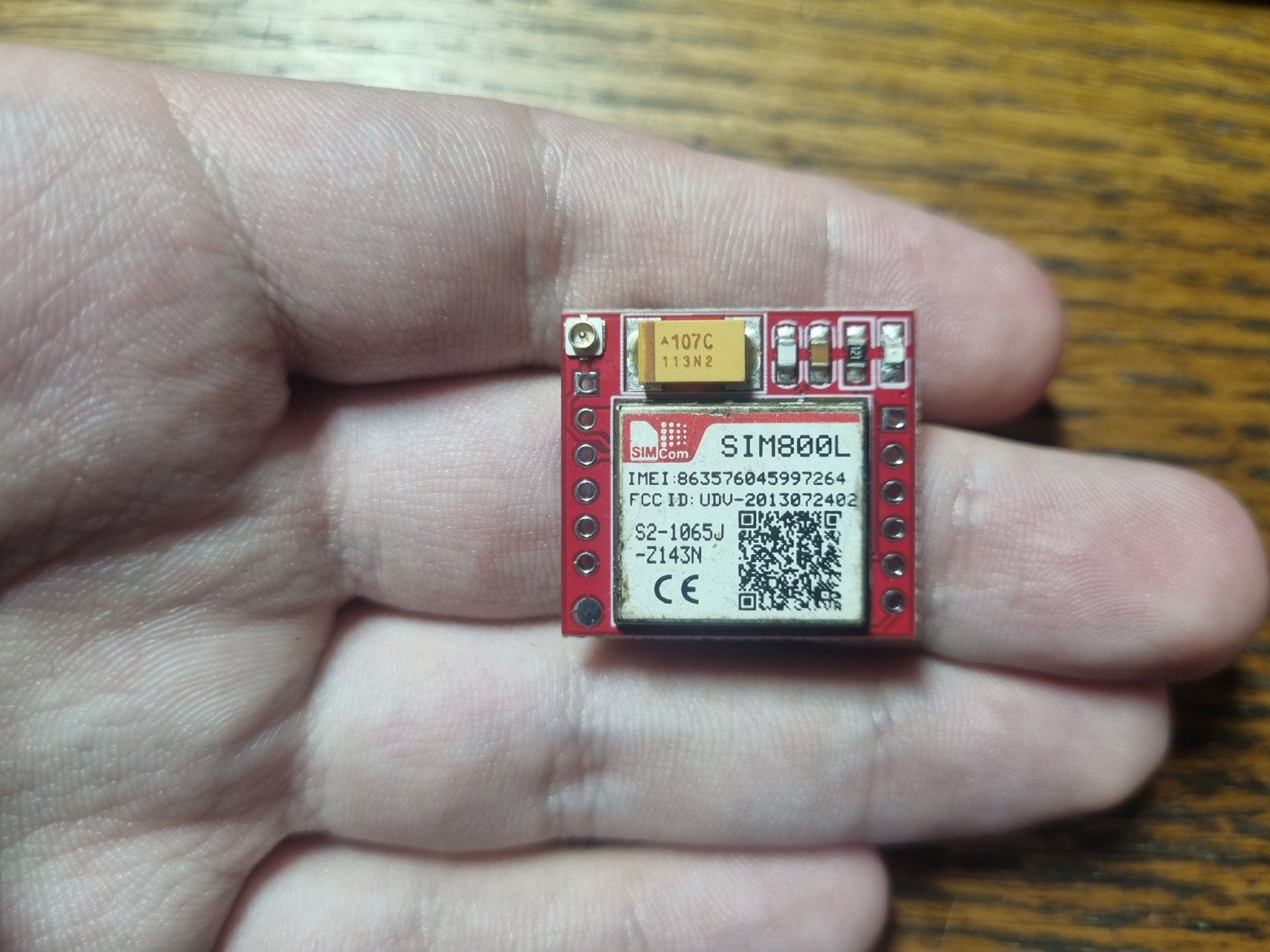
- SIM800L GSM module for mobile phone functionality
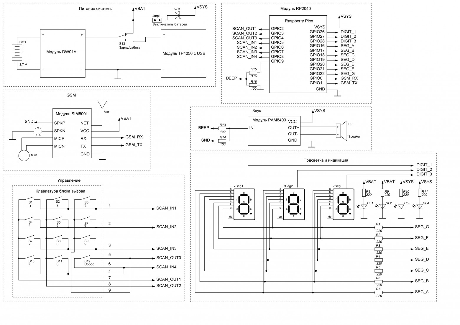
Power is connected through a Schottky diode to protect the battery from charging when USB is connected with the power switch activated. The GSM module's power draw can spike to several amps during network search, requiring attention to battery protection board specifications.
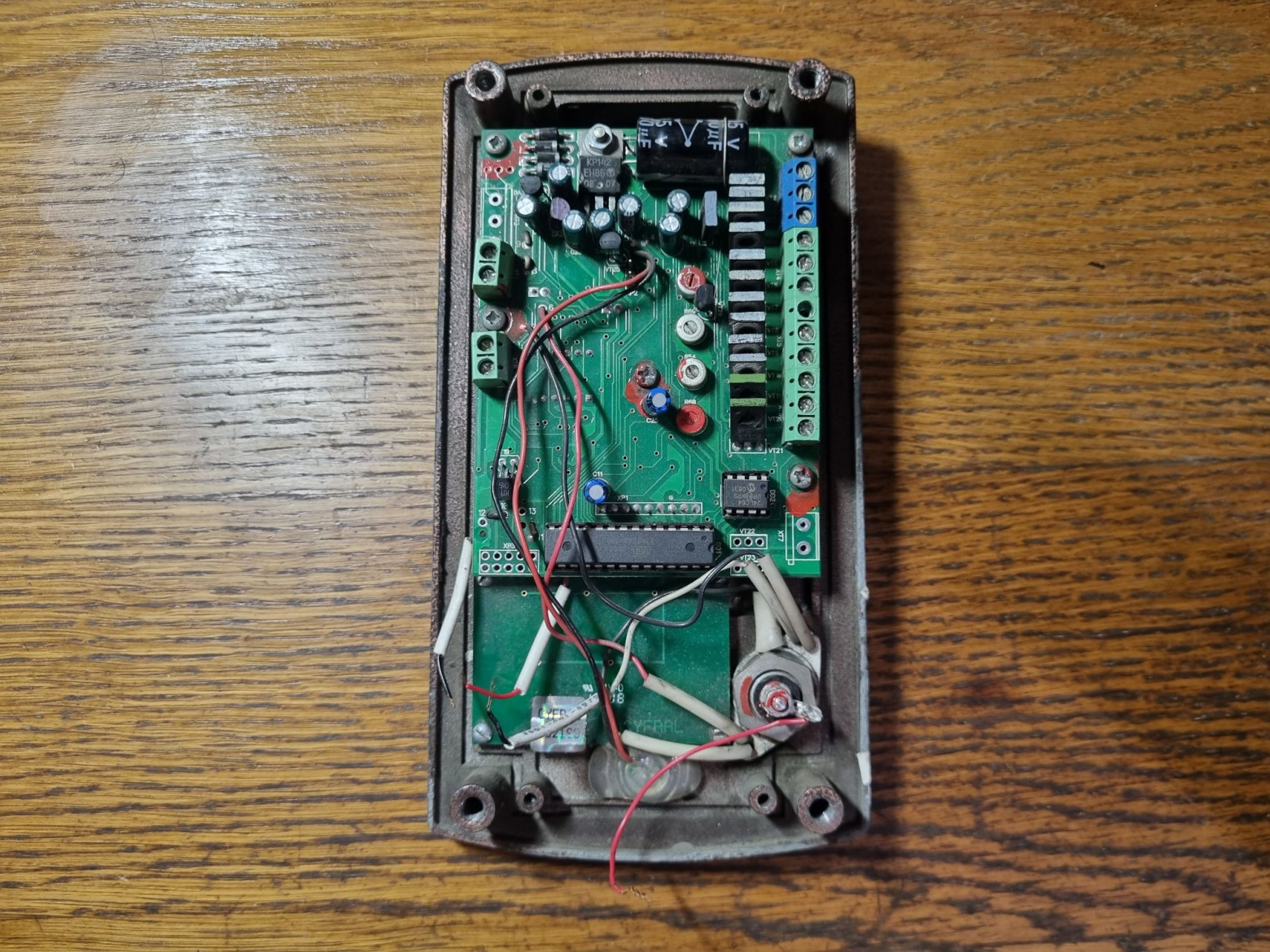
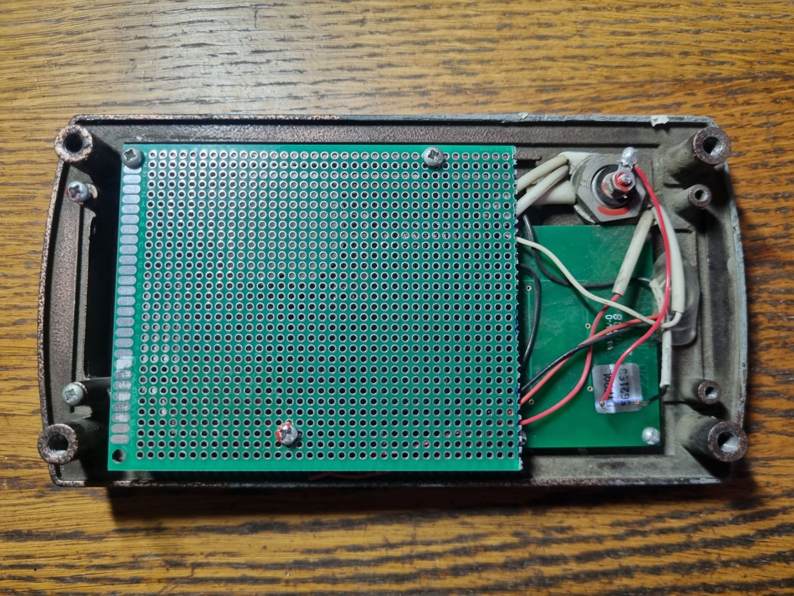
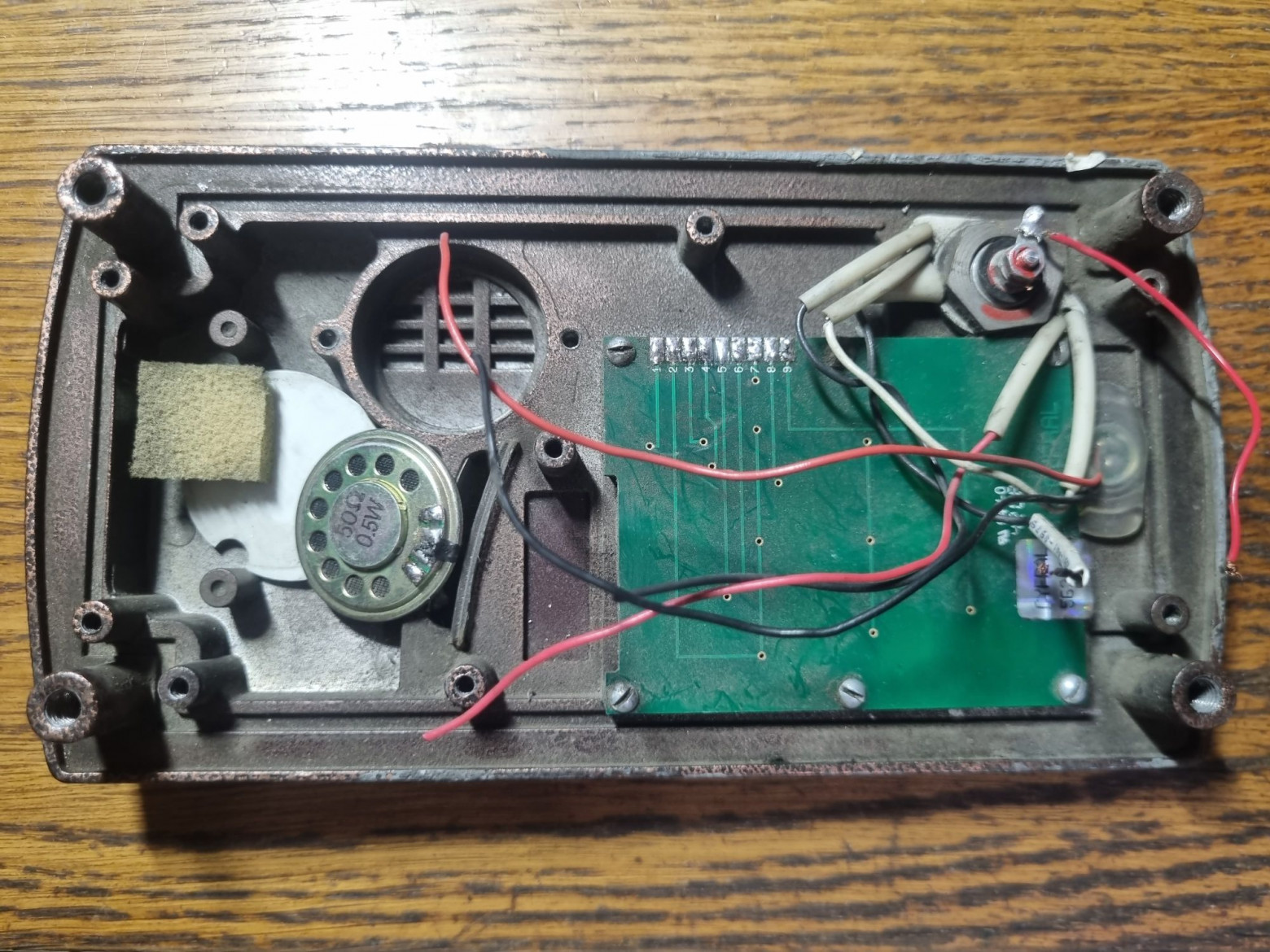
Disassembling the Intercom
The original board was removed and saved for potential restoration of other broken devices. The housing and keypad remained untouched.
Circuit Design
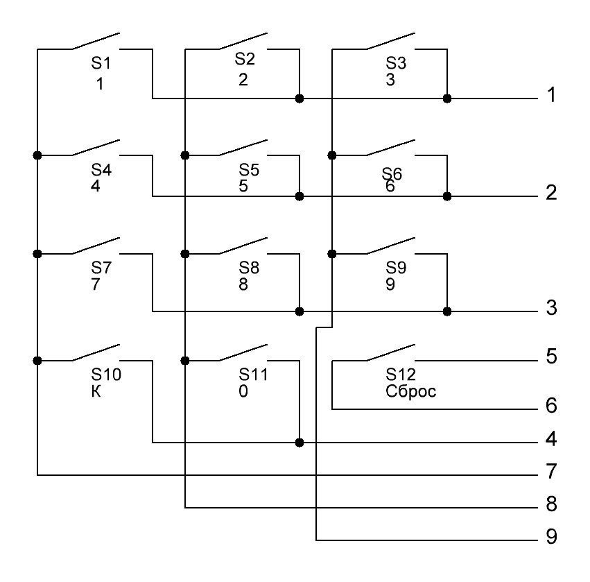
The intercom's keypad is not fully matrix-based — the reset button is connected separately, since in the original design it performs a controller reboot rather than sending a command. The schematic uses a Schottky diode on the lithium battery input to prevent charging when powered via USB.
Assembling the Intercom
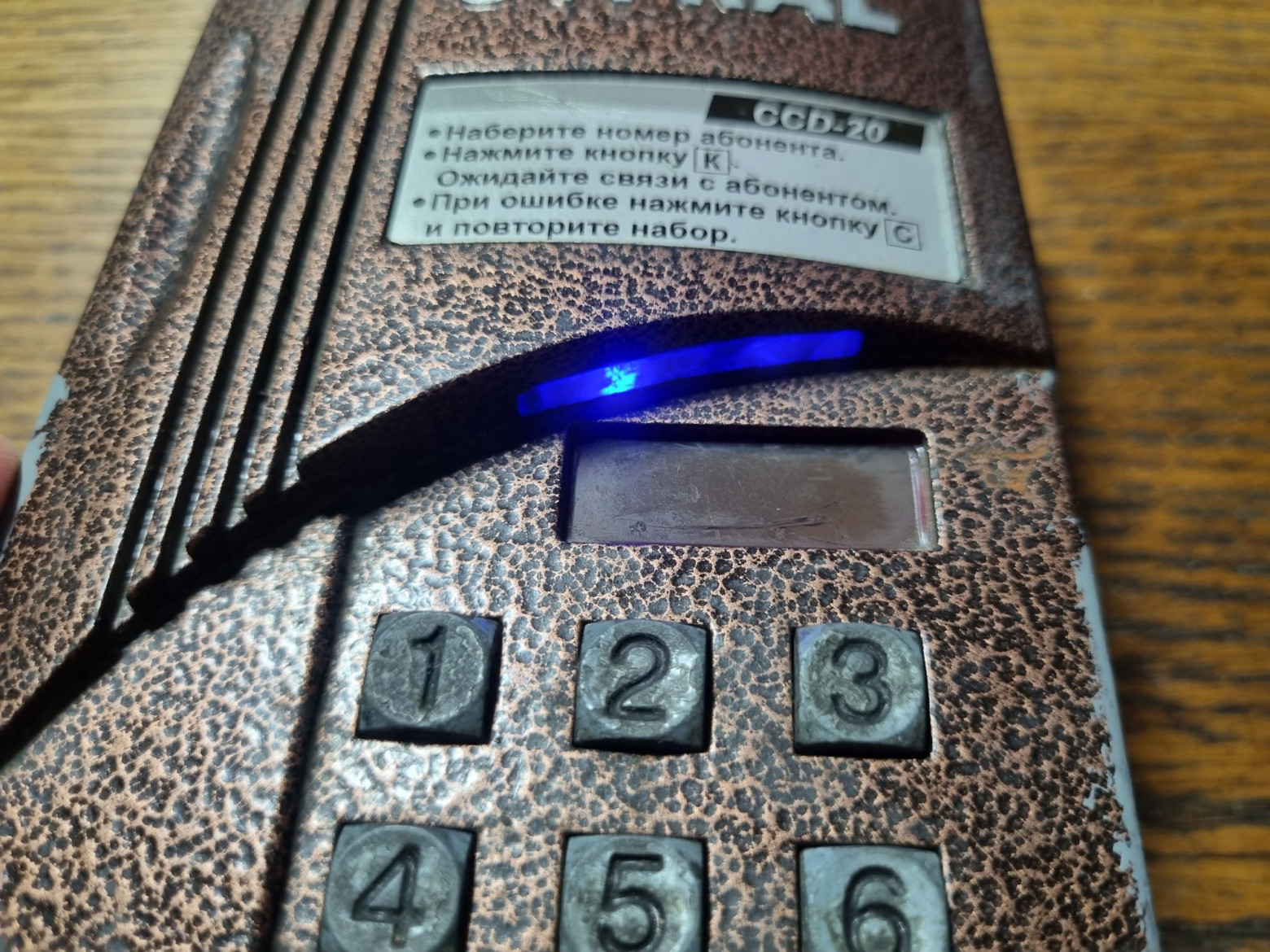
Components were mounted on a green prototyping board, cut to match the size of the original. The backlight was changed from yellow to blue. Most wires were hand-soldered before the final assembly.
Controller Firmware
The main functionality implements call management through AT commands to the GSM module. The code handles the matrix keypad, controls the seven-segment display, and produces tones on button presses.
#define SEG_A 16
#define SEG_B 17
#define SEG_C 18
#define SEG_D 19
#define SEG_E 20
#define SEG_F 21
#define SEG_G 22

#define DIGIT_1 26
#define DIGIT_2 27
#define DIGIT_3 28

#define BEEP 9

#define sim800 Serial1

const byte ROWS = 4;
const byte COLS = 3;
byte rowPins[ROWS] = {5, 6, 7, 8};
byte colPins[COLS] = {2, 3, 4};

char keys[ROWS][COLS] = {
  {'1', '2', '3'},
  {'4', '5', '6'},
  {'7', '8', '9'},
  {'C', '0', 'K'}
};

const byte digitSegments[10] = {
  B00111111, // 0
  B00000110, // 1
  B01011011, // 2
  B01001111, // 3
  B01100110, // 4
  B01101101, // 5
  B01111101, // 6
  B00000111, // 7
  B01111111, // 8
  B01101111  // 9
};

char digitBuffer[3] = {' ', ' ', ' '};
byte bufferIndex = 0;
String numberBuffer = "";

char getKey() {
  char key = 0;
  for (byte c = 0; c < COLS; c++) {
    digitalWrite(colPins[c], LOW);
    for (byte r = 0; r < ROWS; r++) {
      if (digitalRead(rowPins[r]) == LOW) {
        delay(50);
        while (digitalRead(rowPins[r]) == LOW);
        key = keys[r][c];
      }
    }
    digitalWrite(colPins[c], HIGH);
  }
  return key;
}

void displayBuffer() {
  int d1 = (digitBuffer[0] == ' ') ? 10 : digitBuffer[0] - '0';
  int d2 = (digitBuffer[1] == ' ') ? 10 : digitBuffer[1] - '0';
  int d3 = (digitBuffer[2] == ' ') ? 10 : digitBuffer[2] - '0';
  showDigit(d1, DIGIT_1);
  delay(1);
  showDigit(d2, DIGIT_2);
  delay(1);
  showDigit(d3, DIGIT_3);
  delay(1);
}

void showDigit(int digit, int digitPin) {
  digitalWrite(DIGIT_1, HIGH);
  digitalWrite(DIGIT_2, HIGH);
  digitalWrite(DIGIT_3, HIGH);
  if (digit == 10) {
    for (int i = SEG_A; i <= SEG_G; i++) {
      digitalWrite(i, LOW);
    }
  } else {
    byte segments = digitSegments[digit];
    digitalWrite(SEG_A, segments & 0x01);
    digitalWrite(SEG_B, segments & 0x02);
    digitalWrite(SEG_C, segments & 0x04);
    digitalWrite(SEG_D, segments & 0x08);
    digitalWrite(SEG_E, segments & 0x10);
    digitalWrite(SEG_F, segments & 0x20);
    digitalWrite(SEG_G, segments & 0x40);
  }
  digitalWrite(digitPin, LOW);
}

void makeCall(String phoneNumber) {
  sim800.println("ATD" + phoneNumber + ';');
  delay(100);
}

void answerCall() {
  sim800.println("ATA");
  delay(100);
}

void rejectCall() {
  sim800.println("ATH0");
  delay(100);
}

void setup() {
  for (int i = SEG_A; i <= SEG_G; i++) {
    pinMode(i, OUTPUT);
    digitalWrite(i, LOW);
  }
  pinMode(DIGIT_1, OUTPUT);
  pinMode(DIGIT_2, OUTPUT);
  pinMode(DIGIT_3, OUTPUT);
  digitalWrite(DIGIT_1, HIGH);
  digitalWrite(DIGIT_2, HIGH);
  digitalWrite(DIGIT_3, HIGH);
  for (byte c = 0; c < COLS; c++) {
    pinMode(colPins[c], OUTPUT);
    digitalWrite(colPins[c], HIGH);
  }
  for (byte r = 0; r < ROWS; r++) {
    pinMode(rowPins[r], INPUT_PULLUP);
  }
  sim800.begin(115200);
}

void loop() {
  char key = getKey();
  if (key) {
    tone(BEEP, 800, 80);
    if (key >= '0' && key <= '9') {
      digitBuffer[0] = digitBuffer[1];
      digitBuffer[1] = digitBuffer[2];
      digitBuffer[2] = key;
      numberBuffer += key;
    }
    if (key == 'K') {
      if (numberBuffer.length() == 0) answerCall();
      else {
        makeCall(numberBuffer);
        digitBuffer[0] = ' ';
        digitBuffer[1] = ' ';
        digitBuffer[2] = ' ';
        numberBuffer = "";
      }
    }
    else if (key == 'C') {
      digitBuffer[0] = ' ';
      digitBuffer[1] = ' ';
      digitBuffer[2] = ' ';
      numberBuffer = "";
      rejectCall();
    }
  }
  displayBuffer();
}
How Does It Actually Work?
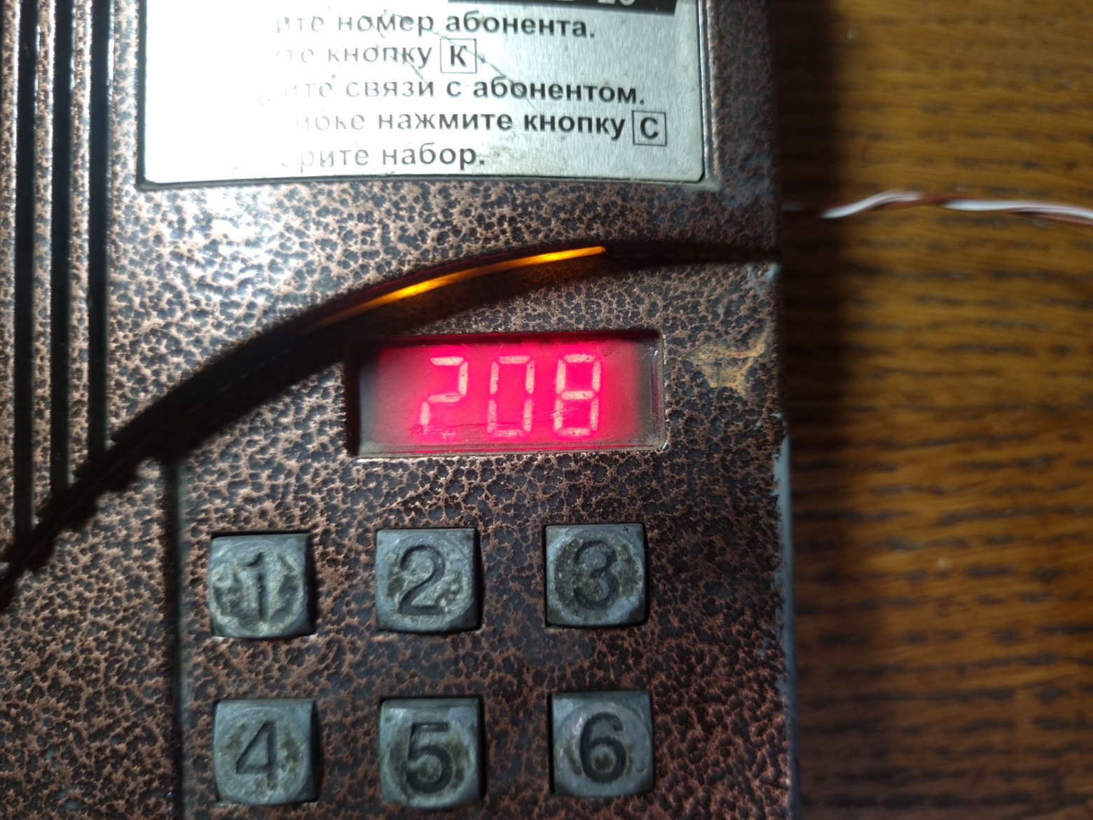
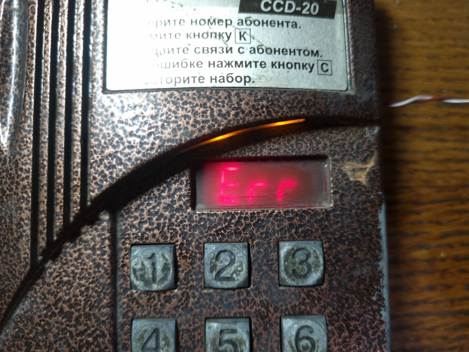
After flashing the firmware, the device is fully functional. Users can dial numbers and make calls using the original intercom's display and keypad. When you press number keys, they appear on the three-digit seven-segment display, scrolling left like on the original intercom. Pressing "K" (call) initiates a GSM call to the entered number. If no number is entered, pressing "K" answers an incoming call. The "C" (cancel) button clears the display and rejects any active call.
The Result
The resulting device works as intended, despite the noise from the PAM8403 amplifier. The SIM800L module not only consumes considerable power but also produces unbearable interference — the noise is roughly twice as loud as the actual signal. Proposed solutions include using signal transformers or alternative amplifiers with isolated analog grounds.
The author plans to add a programming mode, optimize the display and keypad operation using PIO (Programmable I/O on the RP2040), and implement a speed dial function for — naturally — several hundred numbers, to truly honor the "600 apartments" meme.