Nuclear Backlight for a Mechanical Video Wall
Building a 460W ambient backlight system with 2000 independent zones for a triple-screen OLED video wall, featuring custom aluminum frames, 3D-printed parts, and dual-contour LED strips driven by WS2812b controllers.
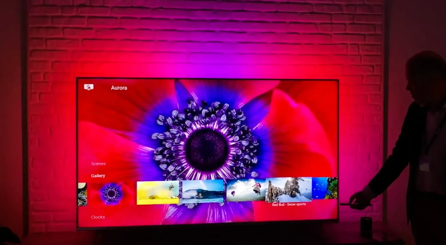
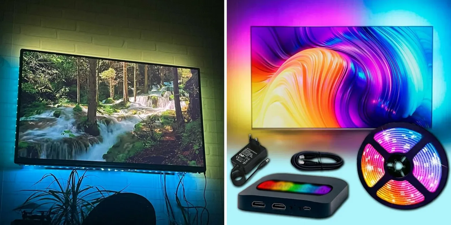
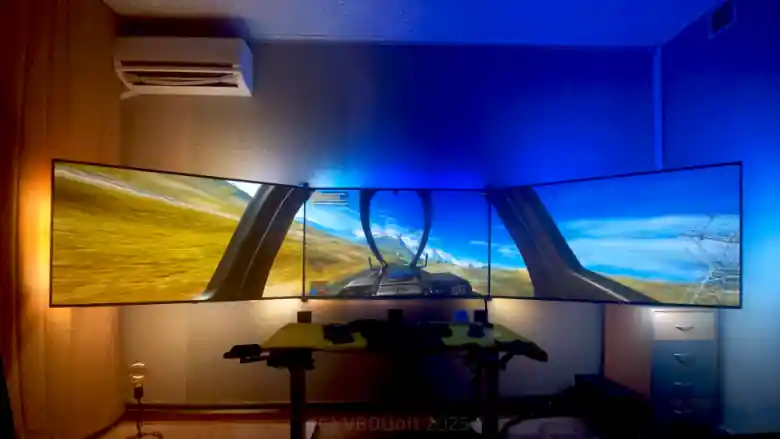
You might have seen Philips Ambilight TVs with their ambient backlight behind the screen. My project takes this concept to its extreme: a 460-watt, 2000-zone backlight for a triple-screen video wall made of LG OLED C1 TVs. This is the story of the mechanical side of that build.
History
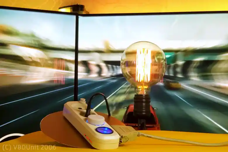
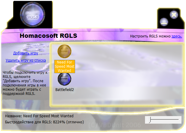
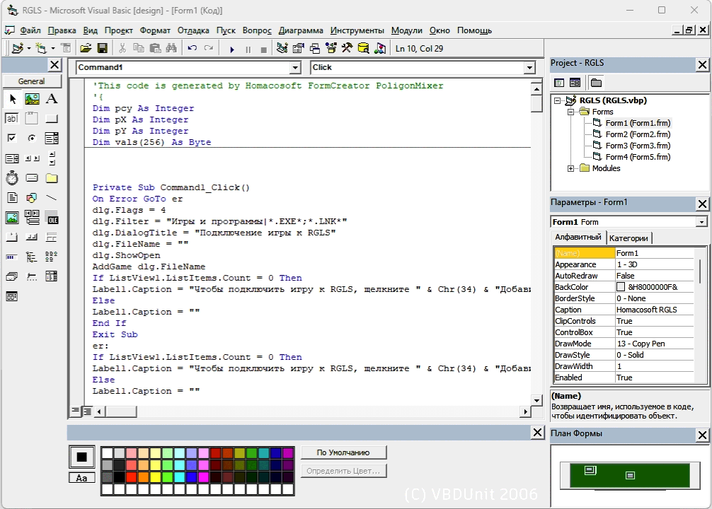
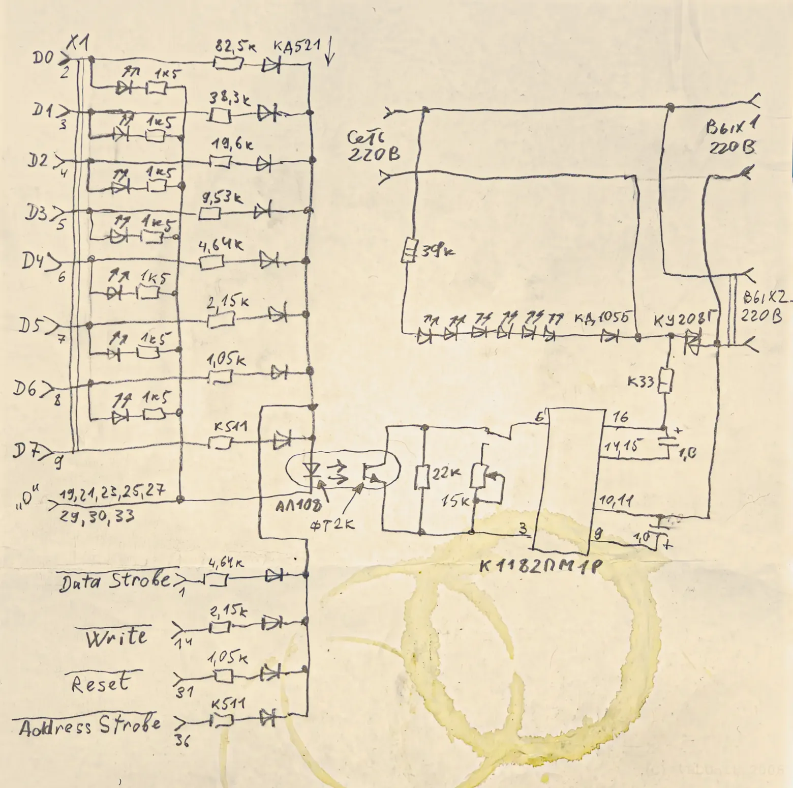
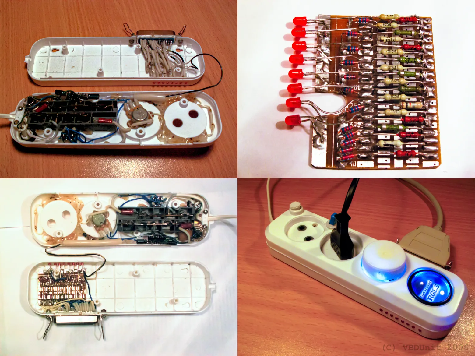
It all started back in 2004, when Philips released Ambilight. I was a teenager, and I built my first prototype: a Visual Basic 6 program that captured the screen and controlled two light bulbs through the printer's LPT port. The hardware was designed by my father — a simple device that adjusted lamp brightness from a single channel of color data. It was crude, but it worked, and I was hooked.
Years later, I returned to the idea — but now with ambitions orders of magnitude larger. Three OLED screens. Thousands of individually addressable LEDs. A custom aluminum frame. And software written in C# that compiles in half an hour and requires 11 GB of RAM.
Three Key Features
What sets this backlight apart from everything else out there? Three things:
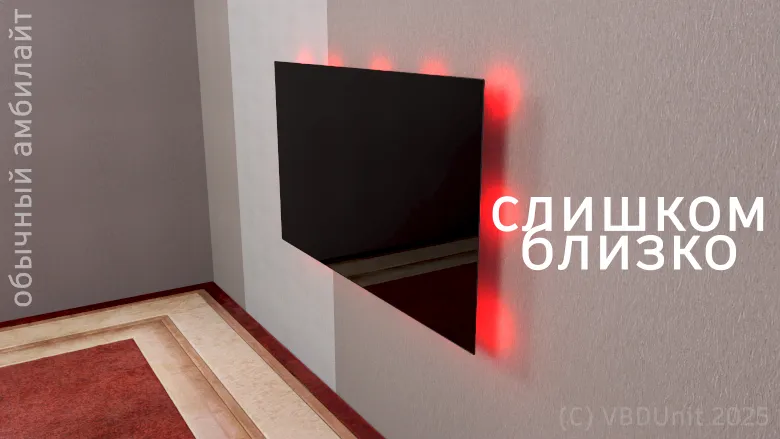
1. Brightness — Works at Any Distance
Most ambient backlights are designed to sit right behind a monitor. They're dim and lose all impact if you move them farther from the wall. My system supports HDR content and can push brightness beyond 100%. Whether the screens are 10 cm or a meter from the wall, the backlight remains visible and effective. At 460 watts, it has headroom to spare.
2. Motion — Light That Moves With the Picture
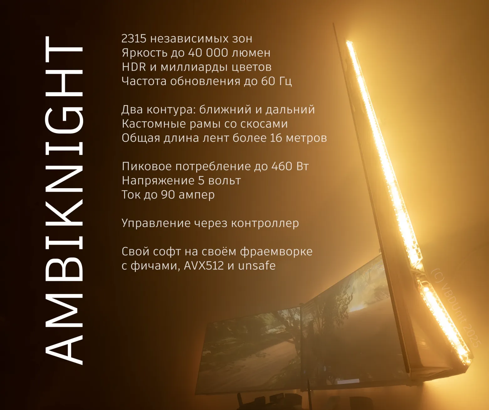
This isn't a static glow. Thanks to the high density of LEDs — over 2000 zones across three screens — highlights and shadows physically travel across the wall in sync with the on-screen action. When a torch swings left in a game, the light on your wall swings left too. When a bright explosion fills the screen, the entire wall flares up. The illusion of the picture "leaking" beyond the bezels is deeply immersive.
3. Gradients — Dual-Contour Illumination
The system uses two independent LED contours: near-field and far-field light. The near-field contour sits close to the screen edges and provides sharp, detailed color mapping. The far-field contour is positioned farther away and creates a soft, diffused glow that fills the surrounding wall. Each channel in each zone uses 32-bit floating point values for color precision, ensuring smooth gradients with no visible banding — even in subtle dark scenes.
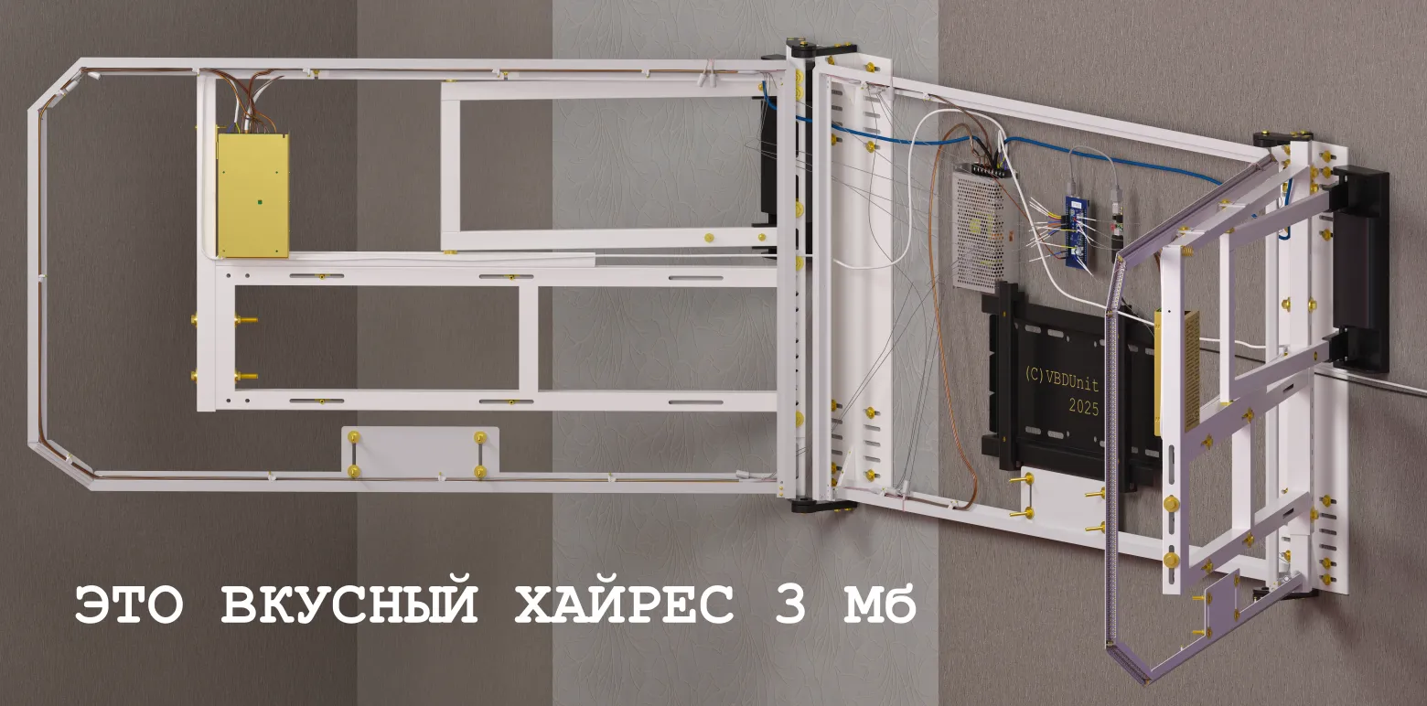
Frame Construction
The mechanical backbone of the system is a set of custom aluminum frames that hold the LED strips in precise positions around each screen. The construction involves:
- 32 aluminum profiles, cut and joined at precise angles
- 36 LED strips (full lengths and cut segments), totaling 16 meters of WS2812b addressable strips
- 3D-printed aluminum parts for complex geometry, particularly the angled bottom sections where standard profiles couldn't fit
- Total frame weight: approximately 2 kg
The LG OLED C-series TVs have a notoriously irregular geometry — the back panel isn't flat, edges taper at different angles, and the stand mounting area creates obstructions. The frame design accounts for all of this with multi-level mounting brackets, 45-degree angled joints, and careful clearance for the side screens, which can pivot on their mounts.
LED Strip Placement
The LED strips run in two rows around each screen: an inner row (near-field) hugging the bezel edge, and an outer row (far-field) positioned several centimeters farther out. The inner row handles per-pixel color detail; the outer row handles broad ambient fill. Both rows are soldered to distribution boards that fan out to the controller network.
Routing the strips was particularly tricky on the side screens, which need some freedom to rotate. I used flexible cable bridges at the pivot points, with enough slack to allow movement without stressing solder joints.
Thermal Management
At full power, the system draws 460 watts — and all of that turns into heat. The aluminum profiles serve double duty as heatsinks. Under normal viewing conditions (movies, general use), temperatures hover around 35°C. During sustained peak brightness (HDR gaming, white screens), temperatures can climb to 70°C — hot, but well within safe limits for the LEDs and aluminum.
The polished aluminum surfaces improve both heat dissipation and light reflection, bouncing more of the LED output toward the wall rather than absorbing it.
3D-Printed Aluminum Parts
For the bottom edges of each screen, where standard profiles couldn't navigate the required compound angles, I turned to 3D-printed aluminum. These parts were designed in CAD and printed by a metal sintering service. They provide both structural support and precise LED positioning in areas where no off-the-shelf extrusion would work.
Assembly and Integration
The frames mount directly to the existing wall-mount brackets behind each TV. Alignment was critical — even a few millimeters of offset between the LED positions and the screen edges would create visible asymmetry in the light patterns. I used adjustable mounting tabs that allow fine-tuning in all three axes after the initial installation.
Cable management was another challenge. With 36 strip segments feeding data and power, the wiring behind the screens is substantial. I used cable channels bonded to the aluminum profiles to keep everything organized and prevent interference between data lines.
What's Next
This article covers only the mechanical side — the frames, strips, and physical construction. The next installment will dive into the controller hardware: how you manage 90 amps of current across 2000 zones, the custom PCB design for the distribution boards, and the power supply architecture that keeps everything running safely.
FAQ
What is this article about in one sentence?
This article explains the core idea in practical terms and focuses on what you can apply in real work.
Who is this article for?
It is written for engineers, technical leaders, and curious readers who want a clear, implementation-focused explanation.
What should I read next?
Use the related articles below to continue with closely connected topics and concrete examples.