The Legendary Ts20 Ampere-Voltmeter: A Soviet Multimeter That Taught Generations of Radio Enthusiasts
A deep dive into the Ts20, the iconic Soviet analog multimeter that became the faithful companion of generations of radio hobbyists. The article covers its elegant circuit design, explains how a single microammeter is transformed into a milliammeter, voltmeter, and ohmmeter using precision resistor networks.
Today, on International Amateur Radio Day, I'd like to tell you about an instrument without which my career as a radio hobbyist would never have happened. I'm talking about the legendary Ts20: a simple, reliable, and affordable ampere-voltmeter that became the best friend and helper of many generations of radio enthusiasts in our country.
I'd been wanting to write about the Ts20 for a long time, but what held me back was not having the instrument on hand. The intention turned into action when I recently and quite by accident discovered a Ts20 in one of Perm's radio parts shops. It was exactly the same type of instrument I'd had once: in a black Bakelite case with ribbed knobs. The only difference was that it was from 1961, not 1958.
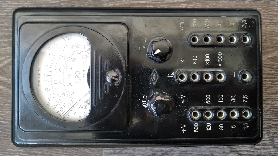
The ergonomic design of the Ts20 tester was as simple as could be. Anyone with experience using analog needle instruments could start working with the Ts20 without glancing at the manual. The image below illustrates this perfectly.
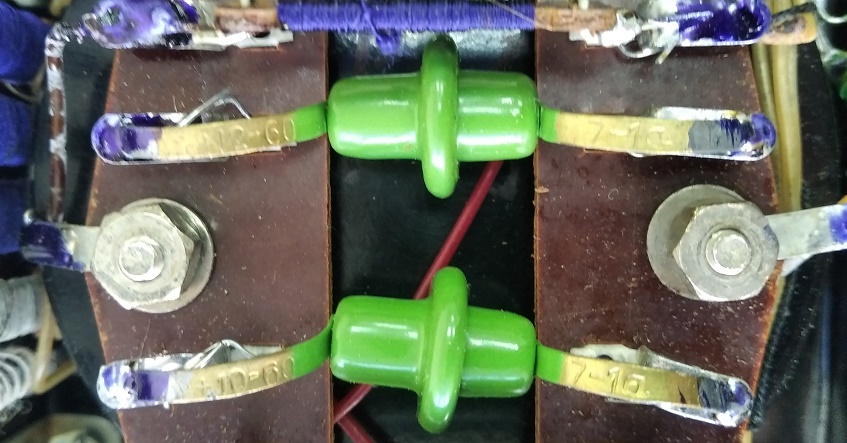
If you remove the bottom cover of the instrument, you can see that the construction is extremely simple, as is the circuit.
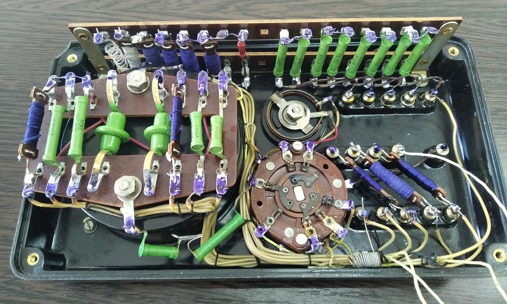
Inside the case we find twenty-seven fixed and one variable resistor; two copper-oxide diodes; a wafer switch with three groups of three positions; and an M494 microammeter. The probe jacks are pressed into the front panel. The battery compartment is located in the bottom cover.
For those who counted fewer than twenty-seven fixed resistors in the photograph, let me clarify: some of them are wire-wound and look like coils wound with wire in blue or gray silk insulation.
Most of the Ts20's circuit components are mounted on textolite panels with pressed-in solder lugs. The assembly is point-to-point wiring, in the best traditions — with leads wrapped around holes in the lugs and paint markings applied to solder joints after quality inspection.
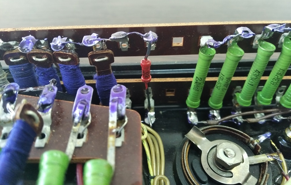
An MLT-0.5 type resistor looks somewhat out of place here, but judging by the quality of the soldering and the paint markings on the joint, it was installed at the factory.
My Ts20 came without probes or documentation. After searching the Internet and doing a bit of reverse engineering by measuring resistor values, I managed to find the schematic matching my particular Ts20 variant.
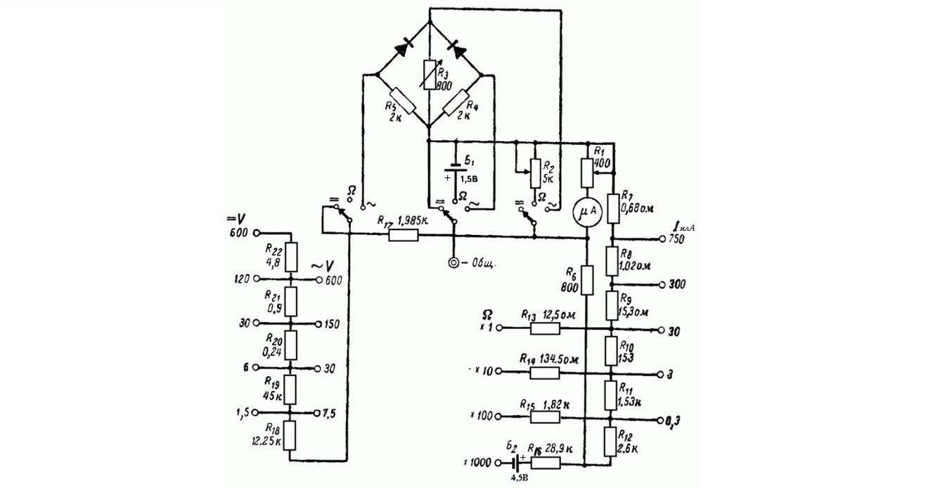
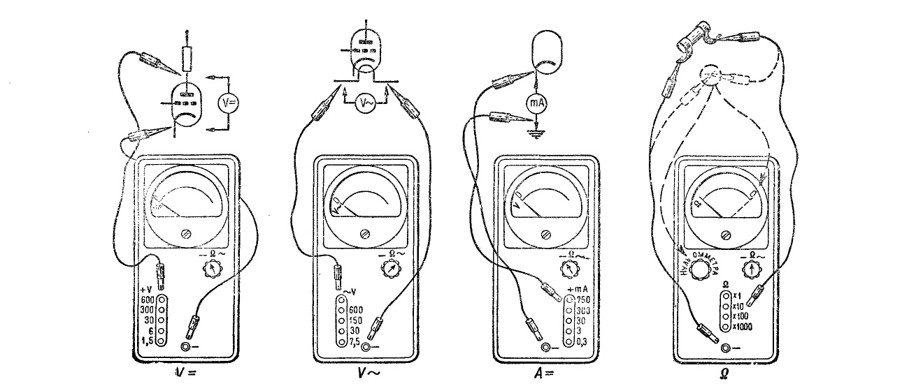
Below, we'll analyze how this circuit works in the modes of measuring DC current, DC voltage, resistance, and AC voltage, using specific examples.
Getting to Know the Needle Microammeter
The core element of the Ts20 ampere-voltmeter is the microammeter.
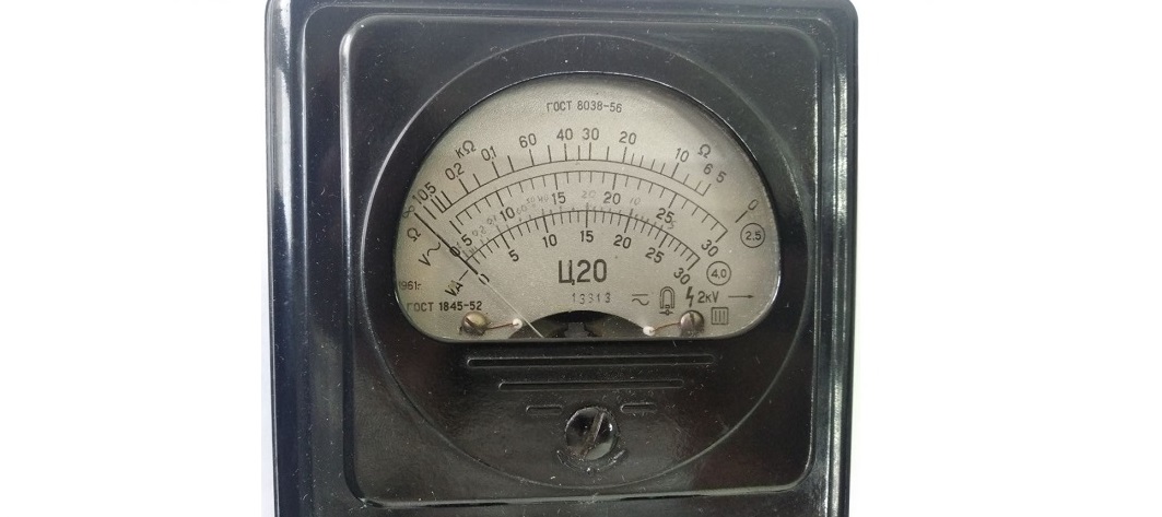
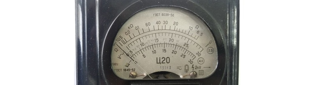
The symbols in the lower right corner of the instrument indicate that it is designed for measurements in DC and AC circuits, that its mechanism type is moving-coil (magnetoelectric with a moving frame), and that the insulation strength was tested at two kilovolts.
Above the serial number 13113 and the type designation "Ts20" are three scales. The "VA–" scale is for measuring current and voltage in DC circuits, while the "V~" scale is for measuring AC voltage. The marking "4.0" in a circle to the right of these scales indicates the instrument's accuracy class for these measurements. Measurement error will be no worse than ±4% of the full-scale value. The "Ω" scale is for measuring electrical resistance to DC with an error no worse than ±2.5%.
From the brief description on page 21 of Radio magazine No. 2 from 1955, we know that the Ts20 uses an M494 microammeter with a full-scale deflection current of 85 μA.
For those who have only encountered needle measurement instruments in physics class, let me explain that the needle of a magnetoelectric microammeter with a moving coil deflects in direct proportion to the current flowing through it.
Accordingly, when a current of 85 μA flows through the M494 microammeter installed in the Ts20, the needle reaches the rightmost mark on the scale (full deflection), and at 42.5 μA it sits at the midpoint. At the zero (leftmost) mark, the needle rests when there is no current. The precise position of the needle "at zero" is set by turning the corrector located below the scale.
The polarity of connecting the magnetoelectric instrument also matters. If you reverse the direction of the measured current, the microammeter's needle will try to turn in the opposite direction. From this we can conclude that when measuring AC circuits, the needle of a magnetoelectric instrument will simply quiver around the zero mark.
Turning the Microammeter into a Milliammeter
The schematic of the Ts20's DC current measurement section is shown below. The mode switch is in the "–" position.
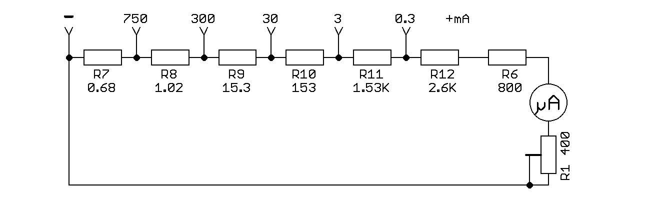
The lowest DC current measurement range on the Ts20 is 0.3 mA (300 μA). This means that at a circuit current of 300 μA, the needle should reach the "30" mark (full deflection) on the "VA–" scale.
It should be noted that "30" here is dimensionless — it indicates the number of scale divisions. Therefore, we need to introduce the concept of "division value" and multiply the scale reading by this value.
In this example, for DC current measurement on the 0.3 mA range with 30 scale divisions, the division value is 0.3 / 30 = 0.01 mA (10 μA).
To understand how a microammeter with a full-scale deflection current of 85 μA can measure a current of 300 μA without being damaged, let's build an equivalent circuit of the Ts20 for measurements on the 0.3 mA range. For the youngest radio enthusiasts, I'll remind you that series-connected resistor values add up, while for parallel-connected resistors, their conductances (the reciprocal of resistance) add up.
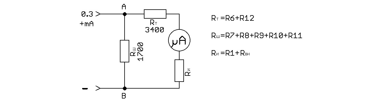
In the figure above, we see a circuit with the shunt resistor Rsh connected in parallel with a chain consisting of the current-limiting resistor Rt, the microammeter, and the resistor Ri, whose resistance equals the sum of the adjustment resistor R1 and the microammeter's internal resistance. In subsequent calculations, we'll assume the microammeter's internal resistance is zero and that R1 equals Ri.
We apply Kirchhoff's rules. For the microammeter needle to be at full deflection, a current of 0.085 mA (85 μA) must flow through it. Therefore, according to Kirchhoff's first rule, the current through the shunt resistor is 0.3 – 0.085 = 0.215 mA (215 μA). The voltage drop across Rsh (1.7 kΩ) equals 1700 × 0.000215 = 0.3655 V. The voltage drop across Rt (3.4 kΩ) equals 3400 × 0.000085 = 0.289 V. Therefore, by Kirchhoff's second rule, the voltage drop across Ri is 0.3655 – 0.289 = 0.0765 V. Applying Ohm's law for a section of the circuit, we get Ri = 0.0765 / 0.000085 = 900 Ω.
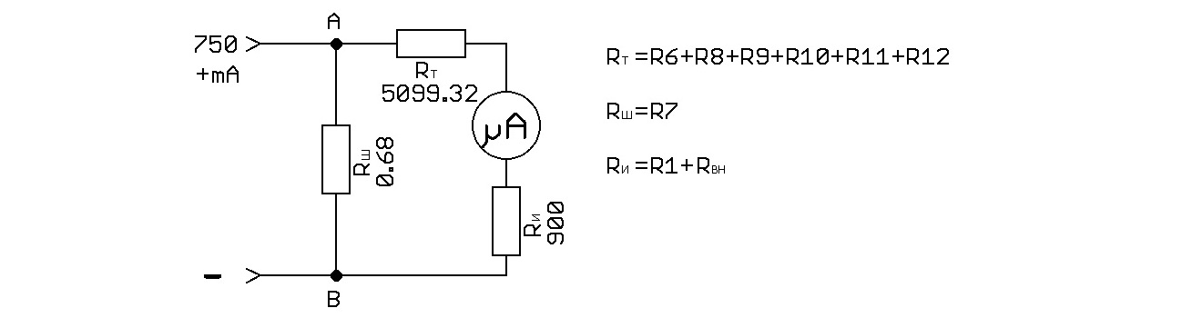
Above is the equivalent circuit of the Ts20 for DC current measurement on the 750 mA range. Rsh = 0.68 Ω, Rt = 5099.32 Ω, Ri = 900 Ω. At full needle deflection, the current through the shunt is 750 – 0.085 = 749.915 mA. The voltage drop across Rsh is 0.68 × 0.749915 = 0.5099422 V. The voltage drop across Rt is 5099.32 × 0.000085 = 0.4334422 V. We verify the voltage drop across Ri: 0.5099422 – 0.4334422 = 0.0765 V — confirming our earlier calculation.
Turning the Microammeter into a Voltmeter
The schematic of the Ts20's DC voltage measurement section is shown below. The mode switch is in the "–" position.
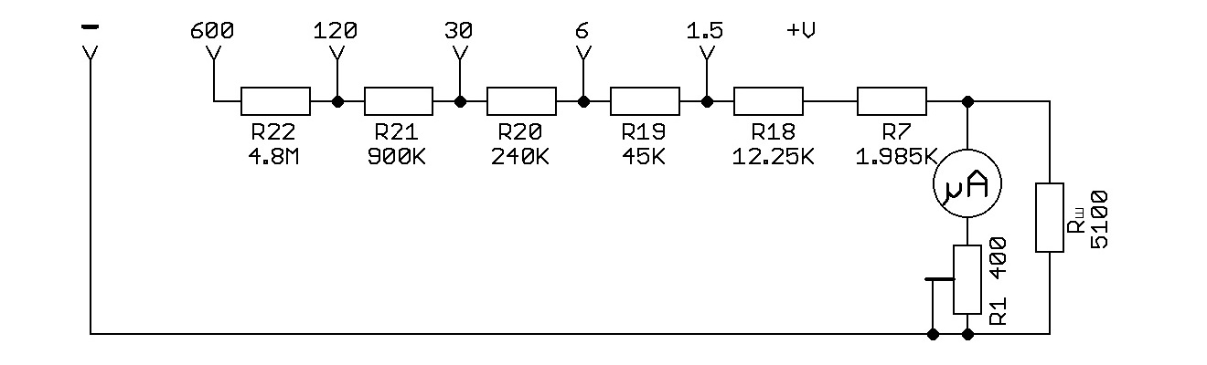
In the circuit, we see that for voltage measurement, the microammeter is connected through a chain of current-limiting resistors. Let's construct the equivalent circuit for DC voltage measurement on the 1.5 V range.
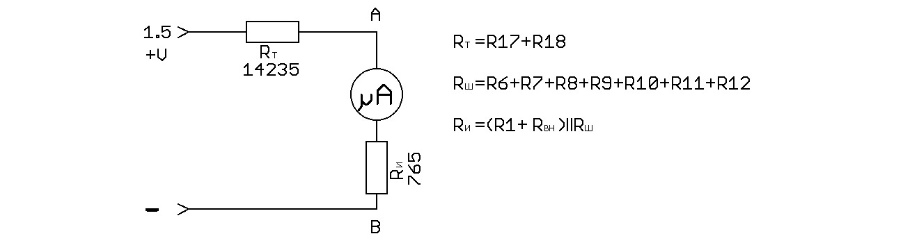
From the previous examples, we know that full needle deflection corresponded to a voltage drop of 0.0765 V between points A and B, with Ri = 900 Ω. Now, however, all shunt resistors R6–R12 with a total resistance of 5100 Ω are connected in parallel with R1 and the microammeter, making Ri = 765 Ω. Dividing 0.0765 V by 765 Ω, we find that for full needle deflection, a current of 100 μA must flow through the instrument terminals.
Thus, when measuring voltage on the 1.5 V range, the Ts20's internal DC resistance is Rt + Ri = 14235 + 765 = 15 kΩ (10 kΩ/V), and the current flowing through the instrument does not exceed 100 μA.
Turning the Microammeter into an Ohmmeter
The simplest ohmmeter could be made by adding a 1.5 V battery to the voltmeter equivalent circuit and making Rt variable. But the Ts20's designers took a different path and adapted the milliammeter circuit for resistance measurement. The mode switch is in the "Rx" position.
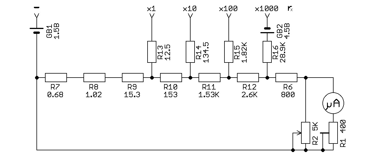
To measure resistance from 5 to 500 Ω, we first short the probes inserted in the "–" and "×1" jacks and use the "SET 0" knob (R2) to set the needle to "zero" (the rightmost mark on the "Ω" scale). Then we connect the probes to the component under test. The greater the measured resistance, the less the needle deflects to the right. If the needle is on the scale to the left of the 0.5 mark, switch to the "×10" range, re-zero on that range, take the measurement again, and switch ranges as needed.
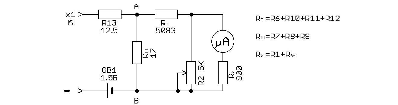
Above is the equivalent circuit for resistance measurement on the "×1" range. Looking at the nonlinear "Ω" scale, where you can only approximate the measured resistance value, there's little motivation to perform calculations on the equivalent circuit.
Measuring Voltage in AC Circuits
As mentioned earlier, measuring AC current directly with a magnetoelectric instrument is impossible. Therefore, the Ts20's AC voltage measurement section includes a rectifier. The mode switch is in the "~" position.
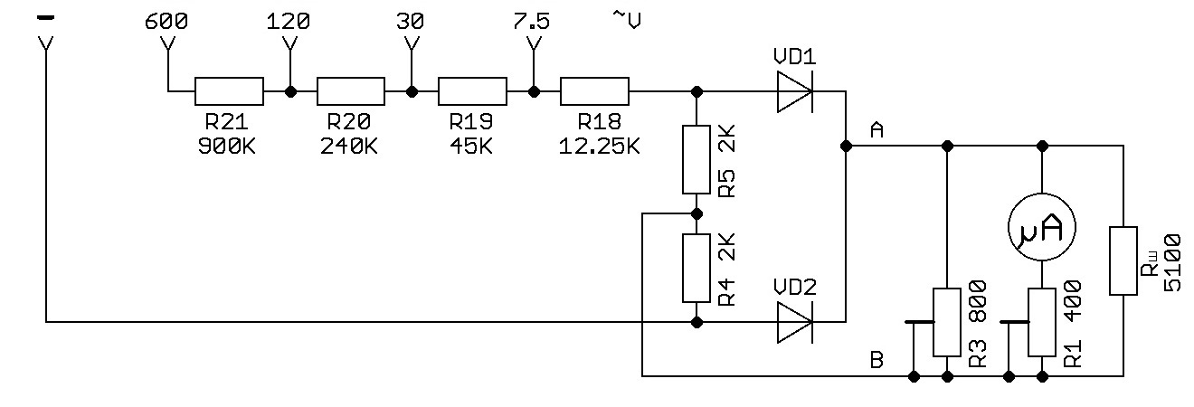
The rectifier circuit is built on diodes VD1, VD2 and resistors R4, R5. In the original schematic, these components are drawn in a diamond shape, but this is not a "diode bridge" as it might appear — it's a full-wave rectifier with a center tap.
This rectifier topology "saves" two diodes but requires two identical secondary windings connected in antiphase in the power transformer. The load is connected between the diode cathodes and the "center tap" of the secondary winding. In the schematic above, the virtual center point, labeled "B," is formed by the voltage divider on resistors R4 and R5. The rectifier's load is the part of the circuit to the right of the diodes.
Given the Ts20's documented internal resistance of 2 kΩ/V across all AC voltage ranges, full needle deflection must be produced by a current of 500 μA flowing through the instrument, and the resistance of the circuit between the diode anode connection points must be 2.75 kΩ. The voltage drop across this section at full deflection is 1.375 V.
Full deflection corresponds to a voltage drop of 0.0765 V between points "A" and "B," which is achievable with a forward diode voltage of approximately 0.6 V.
Judging by their appearance and markings, my Ts20 uses VKV-7-1a copper-oxide diodes. And the most frustrating part is that there is no reference data for them anywhere. We can only learn their forward voltage by desoldering them from the circuit. In later Ts20 modifications, germanium D2 diodes were used instead, followed by D9 diodes.
From the Author
My Ts20 served me faithfully for just over ten years. When it finally couldn't survive yet another fall from the desk, I already had a digital multimeter — the "Elektronika MMTs-01" — but the feelings I experienced were like losing a friend.
Some readers, who have never been rapped on the knuckles with a slide rule, may find the detailed analysis of the Ts20's operation via equivalent circuits to be excessive. My answer is that this is all a tribute of respect to the designers. Remember that around the mid-1950s, when this instrument was being developed, engineers did their calculations on slide rules and mechanical calculators, or even by hand on paper. Moreover, the VS-0.5 type resistors used in the Ts20 circuit had, judging by the "II" marking on their cases, a tolerance of ±10%, yet collectively they had to ensure an instrument accuracy class of 4.0. And the Ts20 cost only 19 rubles 50 kopecks. That's a nontrivial engineering challenge, and the solution absolutely deserves respect.
A well-thought-out design, mechanical durability — especially after the Bakelite case was replaced with polystyrene — and a budget price: these are the three ingredients of the universal love and very long lifecycle of this instrument.
I sincerely hope that after reading this article, experienced radio hobbyists will recall many fond memories, and young radio enthusiasts will understand the old ham radio meme: "Now try to align that with just a Ts20."
From the bottom of my heart, I congratulate everyone on International Amateur Radio Day and the centennial anniversary of the International Amateur Radio Union (IARU)!
73! de RD9F
Sources
- Radio, 1955, No. 2
- Sobolevsky A. G. Testers and Avometers — Moscow: Gosenergoizdat, 1963
- Borisov V. G. The Young Radio Hobbyist. 6th ed. — Moscow: Energia, 1979
FAQ
What is this article about in one sentence?
This article explains the core idea in practical terms and focuses on what you can apply in real work.
Who is this article for?
It is written for engineers, technical leaders, and curious readers who want a clear, implementation-focused explanation.
What should I read next?
Use the related articles below to continue with closely connected topics and concrete examples.