It's complicated about simple things. The most popular L2 headers of the OSI model in Ethernet
Greetings, colleagues! My name is @ProstoKirReal. Today we will discuss headers related to the L2 layer of the OSI model in an Ethernet frame. ❯ Why is this article needed? I often find myself needing to quickly find information about various protocols and their headers, so I dec
Editor's Context
This article is an English adaptation with additional editorial framing for an international audience.
- Terminology and structure were localized for clarity.
- Examples were rewritten for practical readability.
- Technical claims were preserved with source attribution.
Source: original publication
Greetings, colleagues! My name is @ProstoKirReal. Today we will discuss headers related to the L2 layer of the OSI model in an Ethernet frame.
❯ Why is this article needed?
I often find myself needing to quickly find information about various protocols and their headers, so I decided to create a kind of “cheat sheet” that I could return to again and again. I plan to publish two articles on this topic. In the first one, which you are reading now, we will discuss headers at the data link level (L2) models OSI. In the second article we will analyze headers at network levels (L3) and transport (L4).
❯ Why don’t I consider higher levels?
At the moment, there are already high-quality materials on é from other authors who analyze the levels above in detail, especially in the context of programming (for example, HTTP/HTTPS). Therefore, I decided not to repeat myself and focus on less covered aspects that are no less important for understanding network interactions.
❯ Headings at L2 level
IN this In this article we will look in detail at what headers are included in an Ethernet frame at the L2 level. Let me remind you that the Ethernet specification was first developed by a group of companies Digital Equipment Corp, Intel and Xerox (Ethernet DIX). The most popular specifications these days are Ethernet II, IEEE 802.3, and IEEE 802.3 with SNAP header.
Ethernet II
Ethernet II, also known as DIX Ethernet, is the most common Ethernet frame format. It uses a type field (EtherType) to indicate the top-layer protocol, making it useful for encapsulating different protocols. Ethernet II supports IPv4, IPv6, ARP, RARP and PPPoE protocols.
IEEE 802.3
IEEE 802.3 defines standard Ethernet frames that use a Length field to indicate the size of the data. This standard describes the physical and link layers of Ethernet and supports protocols using LLC and SNAP.
IEEE 802.3 with SNAP header
IEEE 802.3 with SNAP (Subnetwork Access Protocol) header is used to encapsulate various network protocols into IEEE 802.3 frames. SNAP allows you to specify a larger set of protocols through additional fields in the header. This format is needed to encapsulate protocols such as IPX, AppleTalk, CLNP and SNA.
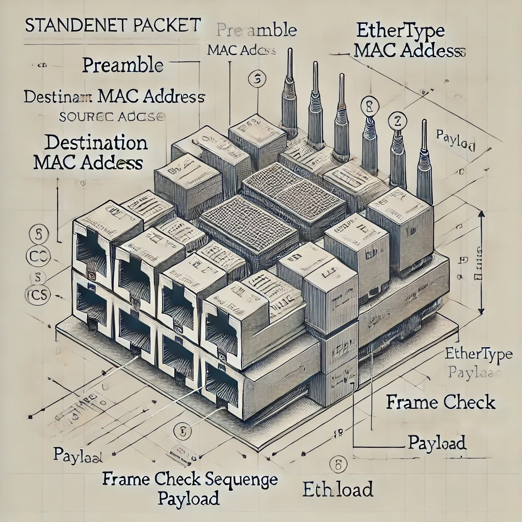
❯ Ethernet frame structure

Preamble
The first element in the frame is the preamble, which is a sequence of bits that is used to synchronize the receiver with the transmitter. The preamble consists of 7 bytes of alternating ones and zeros (10101010) and one byte that ends with the sequence 10101011. The preamble helps devices prepare to receive data by synchronizing their internal data transmission clocks.
In IEEE Ethernet 802.3 and IEEE 802.3 with SNAP, an additional SD or SFD (Start of Frame Delimiter) field is allocated.
In essence, the sequence of bytes and the function of the preamble have not changed, but a separate field has been allocated, indicating the end of the preamble and the beginning of the frame itself.
Why can't we see the preamble in Wireshark?
In Wireshark, the preamble and the SD (Start of Frame Delimiter) field are not displayed, since they do not carry any semantic load for traffic analysis.
MAC addresses
After the preamble in the Ethernet frame there are MAC addresses:
Dst MAC address (destination address) - determines who the frame is intended for.
Src MAC address (source address) - determines who the frame is coming from.
The MAC address consists of 6 bytes (48 bits). The first three bytes identify the manufacturer of the network device, and the second three bytes are the device's unique identifier.
EtherType
The EtherType field in Ethernet II is 2 bytes long and indicates the upper layer protocol type (for example, IPv4 (0x0800), ARP (0x0806), IPv6 (0x86DD). At the receiving end, this field helps determine how to process the data.
All EtherTypes can be found by this link. But in current realities, most types are no longer used and the most popular are ARP, IPv4 and IPv6.
Payload
After EtherType there is payload, which includes headers and upper-level information.
❯ Checksum (FCS)
A checksum, or FCS (Frame Check Sequence), is a method of checking the integrity of data. FCS is used to detect errors that may occur during data transmission and is calculated using the CRC-32 algorithm.
VLAN tag (IEEE 802.1Q)

If it is necessary to divide one physical network into logical networks, a VLAN tag is added to the frame, which is located between the source MAC address and the EtherType field. The IEEE 802.1Q tag contains:
• Tag Protocol Identifier (TPID) (2 bytes): A value of 0x8100 indicates the presence of a VLAN tag.
• Tag Control Information (TCI) (2 bytes): Contains information about frame priority, VLAN ID and other parameters.
TCI includes:
Priority Code Point (PCP) (3 bits) - indicates the priority of the frame.
Canonical Format Indicator (CFI) (1 bit) - indicates the frame format.
VLAN Identifier (VLAN ID) (12 bits) - Identifies the VLAN.
Priority Code Point (PCP) in IEEE 802.1Q
The Priority Code Point (PCP) field in IEEE 802.1Q is a 3-bit field used to indicate the priority of a frame. It allows network devices to distinguish and process traffic with different priority levels, which is important for quality of service (QoS) management. PCP values range from 0 to 7 and determine the priority of traffic processing, with 7 being the highest priority and 0 being the lowest.
Priority Code Point (PCP) values
Each PCP value corresponds to a specific class of service, allowing network administrators to configure traffic processing rules based on the type of data and its importance. Here is more detailed information about PCP values:
0. (Best Effort): standard priority for most data that does not require special delivery conditions. This traffic is processed as resources become available.
Examples: normal web traffic, background downloads.
1. (Background): Low priority for data that can be delayed without serious consequences. Used for background tasks that are not time critical.
Examples: data backup, file synchronization.
2. (Excellent Effort): Slightly higher priority than Best Effort. Used for traffic that is important but not time critical.
Examples: email transactions, file sharing.
3. (Critical Applications): Medium priority for traffic that requires timely delivery. Used for applications that depend on specific time frames.
Examples: enterprise applications, database transactions.
4. (Video, < 100 ms latency): High priority for latency-sensitive traffic. Used for video data requiring low latency.
Examples: video conferencing, video streaming.
5. (Voice, < 10 ms latency): Very high priority for traffic that is extremely latency sensitive. Used to transmit voice data that requires minimal latency.
Examples: VoIP (Voice over IP), online calls.
6. (Internetwork Control): Highest priority for traffic related to network management and control. Used for critical network protocols and control systems.
Examples: routing protocols, network updates.
7. (Network Control): Highest priority for critical network traffic. Used for network infrastructure management and critical system messages.
Examples: time synchronization protocols, emergency notifications.
Setting up prioritization
Network devices such as routers and switches can be configured to process frames in a PCP-aware manner. For example, they can provide more bandwidth or reduce latency for high priority traffic (PCP 5-7) and process low priority traffic (PCP 0-2) with lower priority queues.
Canonical Format Indicator (CFI) is a 1-bit field in the IEEE 802.1Q header that specifies the frame format. It is typically used for compatibility between different types of networks, such as Ethernet and Token Ring. In Ethernet frames, this field is usually set to 0. Let's take a closer look at its meaning and use.
CFI field value:
0: Indicates that the frame is in Canonical Format.
1: Indicates that the frame is in Non-Canonical Format.
Canonical and non-canonical formats
Canonical Format used in Ethernet networks. In this format, bytes and bits in MAC addresses are written and transmitted in least significant order (LSB-MSB, Little-Endian). This is the standard way of representing data in Ethernet frames.
Non-Canonical Format used in some other types of networks such as Token Ring. In this format, bytes and bits in MAC addresses are written and transmitted in MSB-LSB, Big-Endian order.
❯ Important explanation
The VLAN is located exactly between the src MAC address and the E-Type.
The value 0x8100 in E-Type, which we can see is the TPID field indicating the VLAN tag.
The VLAN ID is always followed by an E-Type field indicating the upper-layer protocol.
❯ Ethernet 802.3 structure

The headers in this specification are similar to those in Ethernet II, but there are some differences.
As I wrote above in IEEE Ethernet 802.3 and IEEE 802.3 with SNAP, the preamble is also the first header and an additional SD or SFD (Start of Frame Delimiter) field is highlighted at the end, indicating the beginning of the frame.
The EtherType header is used instead Length — frame length.
Field Length (frame length) in an Ethernet frame is used to indicate the size of the payload of the frame. This field plays an important role in network data transmission. Let's look at why this field is needed and how it is used.
Length: Indicates the size of the data field in bytes. For example, if Length = 1500, this means the frame payload is 1500 bytes.
❯ Basic functions of the Length field
Data Size Identification:
• The Length field specifies the exact size of the frame's payload, allowing the receiving device to determine where the payload ends and the Frame Check Sequence (FCS) begins. This is important for correct data processing.
Efficient use of bandwidth:
• Knowing the data size allows network devices to optimize bandwidth usage, minimizing transmission time and improving network performance.
Compatibility and data processing:
• In the IEEE 802.3 standard, the Length field helps determine how to handle frames of different lengths. This is especially useful when working with variable length frames.
Difference with EtherType field
In an Ethernet frame based on the DIX (Ethernet II) standard, instead of the Length field, the EtherType field is used, which indicates the protocol type of the encapsulated data (for example, IPv4, IPv6).
In the IEEE 802.3 standard, the Length field specifies the length of the frame payload.
❯ 802.2 LLC header
So stop. We looked at 802.3, where did 802.2 come from?
The IEEE 802.3 standard, which defines the Ethernet specification, uses the LLC (Logical Link Control) header of the IEEE 802.2 standard to ensure interoperability and support multi-layer network architecture. The main goal of the IEEE 802.2 LLC standard is to provide a unified method of logical communication control that can be used by various types of networks, including Ethernet, Token Ring, and others. It provides an interface between physical data transmission and higher-level network protocols.
Reasons for the appearance of the LLC header in the IEEE 802.3 standard
1. Unification of protocols:
• The LLC header of the IEEE 802.2 standard provides a unified way to handle data at the data link layer across different types of networks. This allows different network technologies to share a common method of logical communication control.
2. Multi-tier architecture support:
• The LLC header allows Ethernet and other networks to be integrated into a multi-layer network architecture, where data can be transmitted and processed at different layers of the OSI network model.
3. Routing and data management:
• The DSAP and SSAP fields in the LLC header allow you to specify destination and source services or protocols, ensuring proper data link layer routing and processing. This is especially important for networks with a large number of protocols.
4. Compatibility:
• The use of the IEEE 802.2 LLC standard in Ethernet (IEEE 802.3) provides compatibility with other network standards that also use LLC.
Basic Functions of an LLC Header
1. Service Identification:
• The DSAP and SSAP fields in the LLC header are used to indicate destination and source services or protocols, ensuring correct routing and processing of data.
2. Logical Link Control:
• The Control field is used to control data flow, acknowledgments, and connection management.
LLC header structure
The LLC header includes three main fields:
DSAP (Destination Service Access Point): 1 byte.
SSAP (Source Service Access Point): 1 byte.
Control: 1 or 2 bytes, depending on the frame type (informational, control or unnumbered).
Description of LLC header fields
1. DSAP (Destination Service Access Point):
• The DSAP field indicates the destination service or protocol of the recipient.
Example values: 0x06 for IP, 0x42 for STP (Spanning Tree Protocol).
2. SSAP (Source Service Access Point):
• The SSAP field indicates the originating service or protocol of the sender.
Example values: 0x06 for IP, 0x42 for STP.
3. Control:
The Control field is used to control the logical connection and can have different formats depending on the frame type:
• information frames (I-frames) used to transmit data and manage confirmations;
• Control frames (S-frames) used to control data flow and confirmations;
• Unnumbered frames (U-frames) are used to establish and terminate logical connections.
LLC header example
When computer A sends data to computer B over Ethernet using LLC, the header might look like this:
• fields DSAP And SSAP indicate services or protocols of the sender and recipient, such as IP;
• field Control controls data transfer, for example contains frame numbers and flow control commands.
The LLC header plays a key role in providing logical control of link layer communications. It helps identify the services and protocols that control data flow and acknowledgments, allowing for efficient and orderly communication between devices on the network.
❯ IEEE Ethernet 802.3 structure with SNAP headers

SNAP (Subnetwork Access Protocol) Header is an extension of the LLC (Logical Link Control) header in network frames. It is used to provide additional information about the protocol encapsulated in the frame. The SNAP header allows the use of protocols that are not supported by the standard DSAP and SSAP fields, and expands the ability to identify protocols.
Key aspects of SNAP Header
1. Purpose:
• The SNAP header is used to identify protocols that cannot be identified using the standard DSAP and SSAP values. This expands the range of supported protocols.
2. Structure:
• The SNAP header is added after the LLC header and has a fixed size of 5 bytes. It includes fields for Organization, Protocol ID, and Protocol Type.
3. SNAP Header Fields:
• Organizationally Unique Identifier (OUI) - 3 bytes. Identifies the organization that assigns the protocol value;
• Protocol Identifier - 2 bytes. Identifies the specific protocol encapsulated in the frame.
Example of using SNAP Header
The SNAP header is often used in Ethernet frames to encapsulate protocols such as IPX or AppleTalk that do not have standard DSAP and SSAP values.
Example frame structure with LLC and SNAP header
Preamble | SFD | Destination MAC address | Source MAC address | Length/Type | LLC Header (DSAP | SSAP | Control) | SNAP Header (OUI | Protocol Identifier) | Data | FCS |
• DSAP: Typically set to 0xAA, indicating the use of SNAP.
• SSAP: Typically set to 0xAA, indicating the use of SNAP.
• Control: Typically set to 0x03, indicating an unnumbered frame.
• OUI: Organization ID (for example, 0x000000 for standard protocols).
• Protocol Identifier: Protocol specific identifier (eg 0x0800 for IPv4).
Example frame with SNAP for IPv4
Preamble | SFD | Destination MAC address | Source MAC address | Length/Type | DSAP (0xAA) | SSAP (0xAA) | Control (0x03) | OUI (0x000000) | Protocol Identifier (0x0800) | Data | FCS |
The SNAP header extends the capabilities of the LLC header by allowing additional protocols to be identified and encapsulated that are not supported by the standard DSAP and SSAP fields. This provides greater flexibility and interoperability in network technologies, supporting a wider range of protocols and services.
❯ Conclusion
In conclusion, headers at the L2 layer of the OSI model play a key role in ensuring the correct transmission of data in Ethernet networks. The preamble and SFD help synchronize devices and indicate the start of a frame, MAC addresses identify devices, and the EtherType and Length fields indicate the data type and size. FCS checksum verifies frame integrity, while VLAN tagging and PCP priorities help manage quality of service and create logically isolated networks.
Knowing these headers will help you better understand how Ethernet works and manage your network infrastructure more efficiently.
What header is in the Ethernet frame (Frame) between L2 and L3 level?
This header is informally called L 2.5 or shim header
The term "shim header" is used to describe a header that is inserted between two other headers at different levels of the network model.
MPLS (Multiprotocol Label Switching) header
MPLS (Multiprotocol Label Switching) is a technology used to speed up and control traffic flows in networks.
In the context of MPLS (Multiprotocol Label Switching), the MPLS header is often called the "shim header" due to its location between the link layer (L2) and network layer (L3) headers. It is added on top of the link layer frame and before the network layer header, such as IP.
MPLS header structure
The MPLS header is 32 bits (4 bytes) and includes the following fields:
• Label - 20 bits. Used to route the packet;
• Traffic Class - 3 bits. Denotes priority and quality of service (QoS);
• Bottom of Stack - 1 bit. Indicates whether this label is the last in the label stack (1 is last, 0 is not last);
• Time to Live (TTL) - 8 bits. Used to prevent packet looping.

News, product reviews and competitions from the Timeweb.Cloud team — in our Telegram channel ↩

Why This Matters In Practice
Beyond the original publication, It's complicated about simple things. The most popular L2 headers of the OSI model in Ethernet matters because teams need reusable decision patterns, not one-off anecdotes. Greetings, colleagues! My name is @ProstoKirReal. Today we will discuss headers related to the L2 layer of the OSI model in an Ethernet fram...
Operational Takeaways
- Separate core principles from context-specific details before implementation.
- Define measurable success criteria before adopting the approach.
- Validate assumptions on a small scope, then scale based on evidence.
Quick Applicability Checklist
- Can this be reproduced with your current team and constraints?
- Do you have observable signals to confirm improvement?
- What trade-off (speed, cost, complexity, risk) are you accepting?
FAQ
What is this article about in one sentence?
This article explains the core idea in practical terms and focuses on what you can apply in real work.
Who is this article for?
It is written for engineers, technical leaders, and curious readers who want a clear, implementation-focused explanation.
What should I read next?
Use the related articles below to continue with closely connected topics and concrete examples.