It's complicated about simple things. Physical layer (L1) of the OSI model
Greetings, colleagues! My name is ProstoKirReal , and today I want to discuss with you the physical layer (L1) of the OSI model. Understanding this level is fundamental for everyone who is just starting their journey in network technologies. ❯ What is the physical layer? The Phys
Editor's Context
This article is an English adaptation with additional editorial framing for an international audience.
- Terminology and structure were localized for clarity.
- Examples were rewritten for practical readability.
- Technical claims were preserved with source attribution.
Source: original publication

Greetings, colleagues! My name is ProstoKirReal, and today I want to discuss with you the physical layer (L1) of the OSI model. Understanding this level is fundamental for everyone who is just starting their journey in network technologies.
❯ What is the physical layer?
The Physical Layer is the first and lowest layer of the OSI model. It is responsible for transmitting raw data bits over physical communication media such as cables and radio waves. This layer defines the electrical, mechanical, procedural, and functional characteristics for activating, maintaining, and deactivating physical connections between end systems.
First you need to understand what a data bit is. In the first months of work, I was often confused about the concepts of bits and bytes.
Bit and byte are the two basic units of information in computer systems. The difference between them is as follows:
❯ Bit
- Definition: a bit is the smallest unit of information in computer systems.
- Meaning: can take one of two values: 0 or 1. These values are often interpreted as on or off, true or false.
- Usage: used to represent binary information and operations at the hardware level.
❯ Byte
- Definition: a byte consists of 8 bits.
- Meaning: can represent 256 different values (0 to 255 in decimal or 00 to FF in hexadecimal).
- Usage: widely used to represent data such as characters in text files. For example, each character in the ASCII standard is encoded as one byte.
Approximate comparison:
- Bit: 0 or 1
- Byte: 8 bits (eg 01101010)
There's an old joke to help you remember:
Stirlitz had a fight with a bar visitor and went 1 on 1 with him. At the exit, he saw 8 people with bats. “One byte equals 8 bits,” thought Stirlitz

Above I wrote about the binary and hexadecimal systems. What are they for?
Various network devices, computers, etc. communicate with each other using the binary system.
What should we ordinary people do? Even simple data in binary looks very cumbersome.
For example, the sentence “Hello, world!” looks like 01001000 01100101 01101100 01101100 01101111 00101100 00100000 01110111 01101111 01110010 01101100 01100100 00100001.
To increase the readability of such data sets, the hexadecimal system is used. For example, the sentence “Hello, world!” looks like 48 65 6C 6C 6F 2C 20 77 6F 72 6C 64 21.
Already more readable?
That is, 1 bit is 0, 1 byte is 01001000, in hexadecimal 1 byte is 48.
Hexadecimal number system is a convenient, compact and generally accepted way of representing binary data in computer networks and other areas of computer science. It allows engineers and programmers to work with data efficiently while providing ease of transformation and improved readability.
❯ Advantages of the hexadecimal system
- Ease of conversion: Easy conversion between hexadecimal and binary systems.
- Brief entry: significantly shorter records compared to the binary system.
- Increased readability: easier to understand and analyze when working with low-level data.
- Acceptance in standards: widely used in networking and computer standards.
Difficult? A little more and we'll get to L1.
One more concept that we will need to understand.
❯ Data package
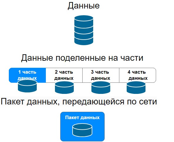
A data packet is a set of information that is transferred between devices on computer networks. It contains data such as text, images, audio or video and information about where and from where this data should be sent. Data packets play a key role in transmitting information across networks.
The package serves us to transfer information from computer to computer. In general, this is a separate topic for conversation; after the OSI model, I’ll start writing an article about data packets.
In short, the data that we need to transmit over the network is divided into several parts. Next, a special header is added to this data (necessary for transmitting packets over the network) and this data packet is transmitted over the network in the form of electrical or light signals.
So, about L1 level.
Network cards in computers and servers are responsible for converting data bits at the first level; SFP modules in network devices such as switches, routers, etc. are used for transmitting packets over the network.
❯ Basic functions of the physical layer
Bit transfer: The physical layer defines how bits of data are transmitted over physical media, whether copper cables, fiber optic cables, or wireless links.
Copper cables transmit information using electrical signals, there are 1G and 10G copper cables, such as twisted pair. I was surprised about the availability of 10G copper.
Fiber optic cables transmit information using light signals.
Wireless, respectively, transmit information wirelessly via radio waves.
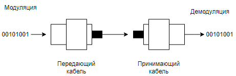
Modulation and demodulation: Converting digital data to analog signals and vice versa.
Modulation and demodulation are processes used to transmit digital data over analog media such as radio waves, telephone lines, or fiber optic cables. These processes play a key role in modern communication systems, including the Internet, mobile networks and television.
❯ Modulation
Modulation is the process of converting digital data (bits) into analog signals that can be transmitted over an analog medium.
❯ Demodulation
Demodulation is the process of converting analog signals back into digital data. The demodulator takes the modulated analog signal and extracts the original digital data from it.
❯ Importance of Modulation and Demodulation
- Efficient data transfer: Modulation allows digital data to be transmitted over analog media such as telephone lines and radio waves, which have limited bandwidth and are subject to noise.
- Compatibility: Thanks to modulation, digital systems can be compatible with existing analogue infrastructure.
- Interference immunity: Different modulation methods can be more resistant to different types of interference and noise, which improves the quality of data transmission.
- Increased throughput: the use of complex modulation techniques such as QAM allows more data to be transmitted per cycle, increasing the overall capacity of the communication channel.
Modulation and demodulation are key processes that enable the transmission of digital data through analogue media, providing efficient, reliable and high-speed communications.
Electrical characteristics: determination of voltages, currents and frequencies used for data transmission.
Voltage determines the potential difference between two network points. Data networks such as Ethernet use different voltage levels to encode digital data. A low voltage can be interpreted as a "0" bit and a high voltage as a "1" bit.
- Current is a flow of charged particles through a conductor. Data networks such as Ethernet use current to carry information. Changes in current can be interpreted as changes in data bit values. Current consumption is also determined by the resistance of the conductors and devices through which the data passes.
- Frequency determines the speed at which data is transferred through the network. In Ethernet and other data networks, frequency determines the speed of data transfer, measured in bits per second (bps). For example, Ethernet can have a frequency of 100 MHz or 1 GHz, which determines the maximum data transfer speed over the network.
Mechanical characteristics: Definition of physical connection, connectors and cables.
Physical Connection: is the way devices on a network physically connect to each other. The physical connection may include different types of cables, connectors, and ports. For example, in local area networks (LANs), devices are often connected using Ethernet cables.
Connectors: - These are physical interfaces that allow you to connect cables to network devices. There are many types of connectors, each designed for specific cable types and protocols. For example:
- RJ45: used to connect twisted pair Ethernet.
- LC/SC: used in fiber optic networks.
The connectors provide a reliable and standardized connection that ensures device compatibility.
Cables: - These are the physical media through which data is transmitted. The cable type determines the data transfer speed, the distance over which the data can be transferred, and the environment in which the cable can be used. Main cable types include:
- Twisted Pair: the most common type of cable for local networks. Includes unshielded twisted pair (UTP) and shielded twisted pair (STP).
- Fiber Optic Cable: used for high-speed connections over long distances. Transmits data using light pulses.
- Each type of cable has its own characteristics, such as bandwidth, resistance to interference, and maximum transmission distance.
❯ Examples of mechanical characteristics in an Ethernet network
- RJ45 connector: used to connect Ethernet cables to network devices such as routers, switches and network cards.
- Optical fiber with LC/SC connectors: used for both high-speed backbone and long-distance connections, as well as short-distance connections (like RJ connectors).
❯ Why is this important
Mechanical performance is important to ensure reliable and efficient connections between devices on a network. They affect:
- Compatibility: The use of standardized connectors and cables ensures that devices can be connected and will work together.
- Performance: The type and quality of cables and connectors can affect data transfer speeds and connection stability.
- Interference immunity: Shielded cables and proper connectors can reduce the impact of electromagnetic interference and improve call quality.
- Physical protection and durability: Robust connectors and cables ensure long-lasting and reliable physical connections, which is especially important in industrial and commercial networks.
- Physical topology: determining the location and connection of network devices.
- The physical network topology defines the physical location and connectivity of network devices such as computers, routers, switches, and cables. This is an important aspect of network design and management because it affects the performance, scalability, reliability, and manageability of the network.
Let's look at the main types of physical topology and their characteristics.
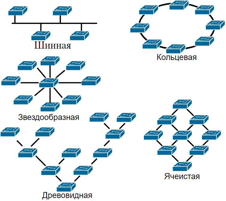
❯ Basic types of physical topology
1. Bus Topology
In this topology, all devices are connected to one common cable (bus). Data transfer is carried out through this cable and all devices can receive this data.
Advantages:
- Easy to install and low cost.
- Ease of adding new devices.
Flaws:
- Limited cable length and number of connected devices.
- A cable failure leads to the failure of the entire network.
- Poor performance with a large number of devices.
2. Star Topology
All devices are connected to a central node (switch or hub). The central node controls the transfer of data between devices.
Advantages:
- High performance as data is transferred through a central node.
- Easy to operate and troubleshoot.
- The failure of one device or cable does not affect the operation of the entire network.
Flaws:
- Dependence on the central node: if it fails, the entire network stops working.
- Higher cost due to the need for a central hub and more cables.
3. Ring Topology
The devices are connected in a ring, and each node is connected to two neighboring nodes. Data is transferred along a ring from one device to another.
Advantages:
- Uniform load distribution between nodes.
- No collisions during data transfer.
Flaws:
- The failure of one device or cable disrupts the entire network.
- Difficulty adding new devices.
4. Mesh topology or mesh topology
In this topology, each device is connected to all other devices. There is a fully mesh topology, where all devices are directly connected to each other, and a partial mesh topology, where some devices are not directly connected.
Advantages:
- High reliability: failure of one device or cable does not affect the operation of the entire network.
- High performance and minimal latency.
Flaws:
- High cost and complexity of installation.
- Difficult to manage and maintain.
5. Tree Topology
Combination of star and bus topologies. Devices are connected into groups, which, in turn, are connected by central nodes.
Advantages:
- The hierarchical structure simplifies management.
- Ease of network scaling.
Flaws:
- Dependence on central nodes.
- More complex installation compared to simple star topology.
❯ Why is physical topology important?
- Performance: Different topologies offer different levels of performance and can handle different volumes of traffic.
- Reliability: topology affects the network's resilience to failures. Some topologies are more resistant to failure of individual devices or cables.
- Scalability: Different topologies handle the addition of new devices and network expansion differently.
- Controllability: Some topologies are easier to manage and troubleshoot.
- Price: The cost of installing and maintaining a network depends on the chosen topology, since different topologies require different amounts of cables and equipment.
Physical network topology plays a key role in the design, management and maintenance of network systems to ensure optimal performance and reliability.
Core Technologies
- Cables and connectors: RJ45, fiber optic cables, coaxial cables.
- Electrical characteristics: RS-232, V.35, 100BASE-TX, 10BASE-T.
- Wireless standards: 802.11 (Wi-Fi), Bluetooth.
Basic Standards
- RS-232: standard for serial data exchange. (this is not a connector as is usually believed, DE-9 is a connector, and RS-232 is a standard)
- V.34: a standard for modems that defines modulation methods for transmitting data over telephone lines at speeds up to 33.6 Kbps.
- 100BASE-TX: standard for data transmission over twisted pair cable at a speed of 100 Mbit/s.
- 802.11: a set of standards for wireless networks.
Using the physical layer in practice
In practice, the physical layer is used to create and maintain physical connections between network devices. For example, when you connect a computer to a router using an Ethernet cable, you are interacting with the physical layer. It is important to understand that any problems with cables or connectors at this level can lead to failures in data transmission.
❯ What happens to the data if you disconnect the cable?
Disconnecting a network cable and its impact on the layers of the network model
When a network cable is pulled out, it only affects the physical layer of the OSI network model, but how does this affect the operation of the TCP/IP protocols?
Physical Layer
The physical layer is responsible for transmitting data over a physical medium such as copper cable or optical fiber. When a network cable is disconnected, devices at this layer lose their ability to transmit signals. This layer can recognize that the cable has been pulled out because the electrical or optical signal is no longer being received.
Data Link Layer (more about this layer in the next article)
Канальный уровень взаимодействует непосредственно с физическим и управляет доступом к среде передачи данных, обнаружением ошибок и управлением потоком. При отключении кабеля сетевой интерфейс, например, Ethernet, сигнализирует об ошибке, такой как «link down». This event is recorded at this level, but is not necessarily passed on higher.
TCP/IP and higher protocols
TCP/IP stack protocols (such as TCP, UDP, IP) operate at higher levels and do not have direct access to information about the physical state of the connection. They operate on virtual representations of the network provided by underlying layers. Therefore, when a cable is disconnected, TCP/IP does not know about it directly unless information about the connection being disconnected is transmitted from lower layers.
Mechanisms for detecting connection loss
In order for upper-level protocols, such as TCP, to know that the connection is broken, special mechanisms are used:
- KeepAlive: Once a connection is established and the KeepAlive option is enabled, TCP begins sending small control packets after a certain period of inactivity. If a certain number of KeepAlive packets do not receive a response, TCP considers the connection invalid and initiates a termination.
- Timeouts: TCP packets have built-in timeout mechanisms that allow you to determine if data has not been delivered within a certain time. If a timeout occurs, TCP attempts to retransmit the data or close the connection.
When a network cable goes down, it is first detected at the physical and data link layers of the network. However, if the disconnect information is not passed upstream, the TCP/IP protocols will not know about it directly. To address this issue, TCP provides mechanisms such as KeepAlive and timeouts to help detect connection loss and take appropriate action. These mechanisms ensure the reliability and resilience of network applications, even during physical network failures.
❯ Conclusion
The physical layer of the OSI model is the basis for all other layers. Without a reliable physical connection, the remaining layers will not be able to perform their functions. Understanding the physical layer will help you effectively troubleshoot and optimize the performance of network devices.
In the next article, we will look at the data link layer (L2) and its role in network communication.
Thank you for your attention, and see you in the next article!
Read also:
- ➤ Network engineer tools: from notepad to smartphone
- ➤ How to prepare for an interview as an aspiring network engineer? Basic knowledge
- ➤ Deploying .NET applications for the little ones
- ➤ I wrote it myself, I flew it myself: how and why did I develop a 3D game from scratch for computers from the 90s in 2024?
- ➤ Vinton Cerf - the man who invented the Internet
News, product reviews and competitions from the Timeweb.Cloud team - in our Telegram channel ↩

Why This Matters In Practice
Beyond the original publication, It's complicated about simple things. Physical layer (L1) of the OSI model matters because teams need reusable decision patterns, not one-off anecdotes. Greetings, colleagues! My name is ProstoKirReal , and today I want to discuss with you the physical layer (L1) of the OSI model. Understandi...
Operational Takeaways
- Separate core principles from context-specific details before implementation.
- Define measurable success criteria before adopting the approach.
- Validate assumptions on a small scope, then scale based on evidence.
Quick Applicability Checklist
- Can this be reproduced with your current team and constraints?
- Do you have observable signals to confirm improvement?
- What trade-off (speed, cost, complexity, risk) are you accepting?
FAQ
What is this article about in one sentence?
This article explains the core idea in practical terms and focuses on what you can apply in real work.
Who is this article for?
It is written for engineers, technical leaders, and curious readers who want a clear, implementation-focused explanation.
What should I read next?
Use the related articles below to continue with closely connected topics and concrete examples.