Hacking an Aerodrome Weather Indicator
A maker's journey to reverse-engineer and reprogram a Soviet-era aerodrome weather indicator from the KRAMS-2 meteorological station, replacing its original interface board with an ESP32 to display live METAR weather data from airports worldwide.
I have mixed feelings about weather stations. On one hand, I dislike typical Arduino projects with tiny screens. On the other hand, unique vintage devices fascinate me. This time, I got my hands on an aerodrome weather indicator from the Complex Radio-Technical Aerodrome Meteorological Station (KRAMS).
KRAMS: Complex Radio-Technical Aerodrome Meteorological Station
Aviation depends on precise weather forecasts for safety. Aircraft altimeters are calibrated based on atmospheric pressure at the airport to ensure proper landing on the runway. Each aerodrome has its own meteorological station. The KRAMS-4 represents a modern Russian aviation meteorological system that combines modularity, ICAO compliance, and integration with dispatch services.
These systems automatically collect critical meteorological data:
- Air temperature and humidity, wind speed and direction, atmospheric pressure
- Meteorological visibility range and cloud ceiling height
- Precipitation type and quantity
Based on this data, automated meteorological reports (METAR, TAF, ATIS) are generated in ICAO standard codes for airport dispatchers and pilots.
METAR Format
Each airport has a four-letter ICAO code. For example: UWGG is the code for Strigino Airport in Nizhny Novgorod. The METAR report contains structured meteorological information in a coded format.
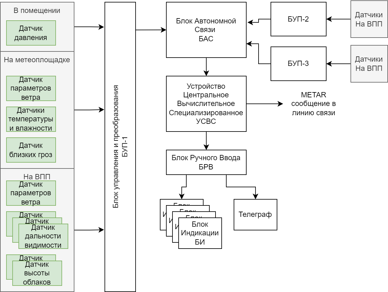
KRAMS-2 System Architecture
The 1980s Soviet KRAMS-2 system was fully automated, providing weather summaries on indicator displays and via telegrams, including METAR format.
The system includes three sensor groups:
- Indoor sensors
- Meteorological site sensors
- Runway area sensors
Signals are processed by a control and conversion unit (BUP), then transmitted to autonomous communication blocks. Multiple BUPs can be connected for multiple runways. The processed data forms meteorological reports in METAR, BI, or SHTORM formats, printed on telegraphic printers, transmitted to other aerodromes, or displayed on indicator panels.
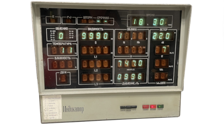
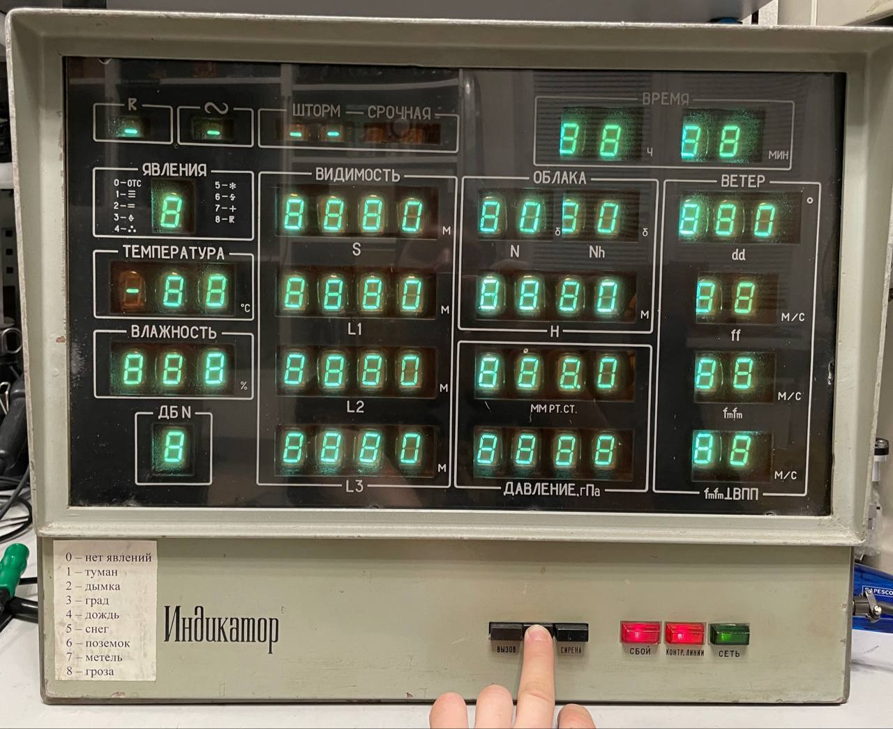
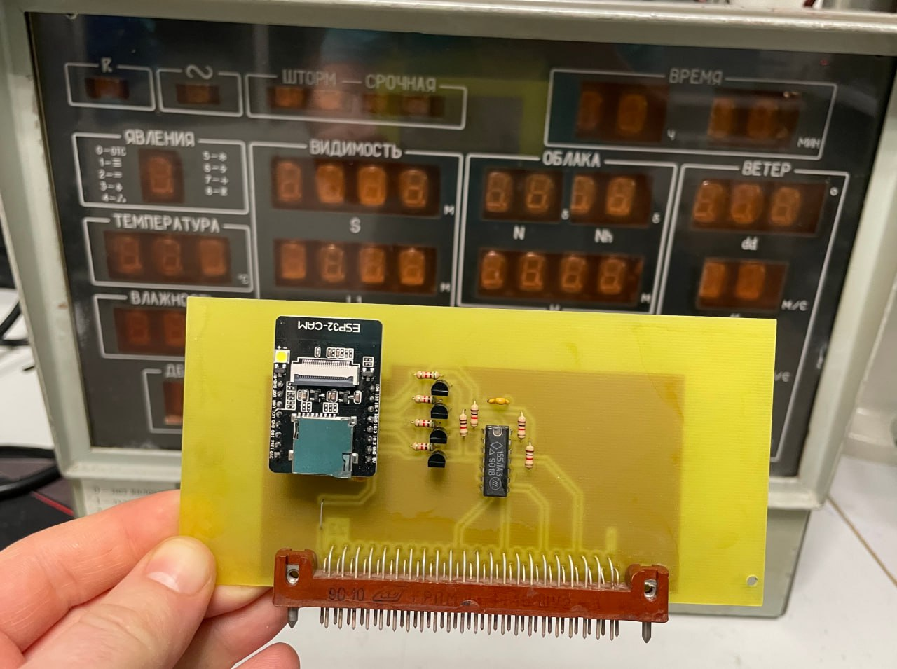
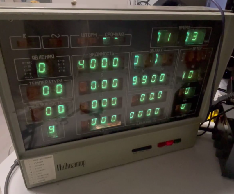
Autonomous Indicator Device
Device specifications:
- Dimensions: 515 x 420 x 150 mm
- Weight: 15 kg
- Steel frame: 1.2 mm thick
- Display: 56 seven-segment vacuum fluorescent indicators (IV-22) with 18 mm digit size
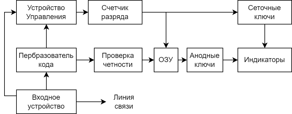
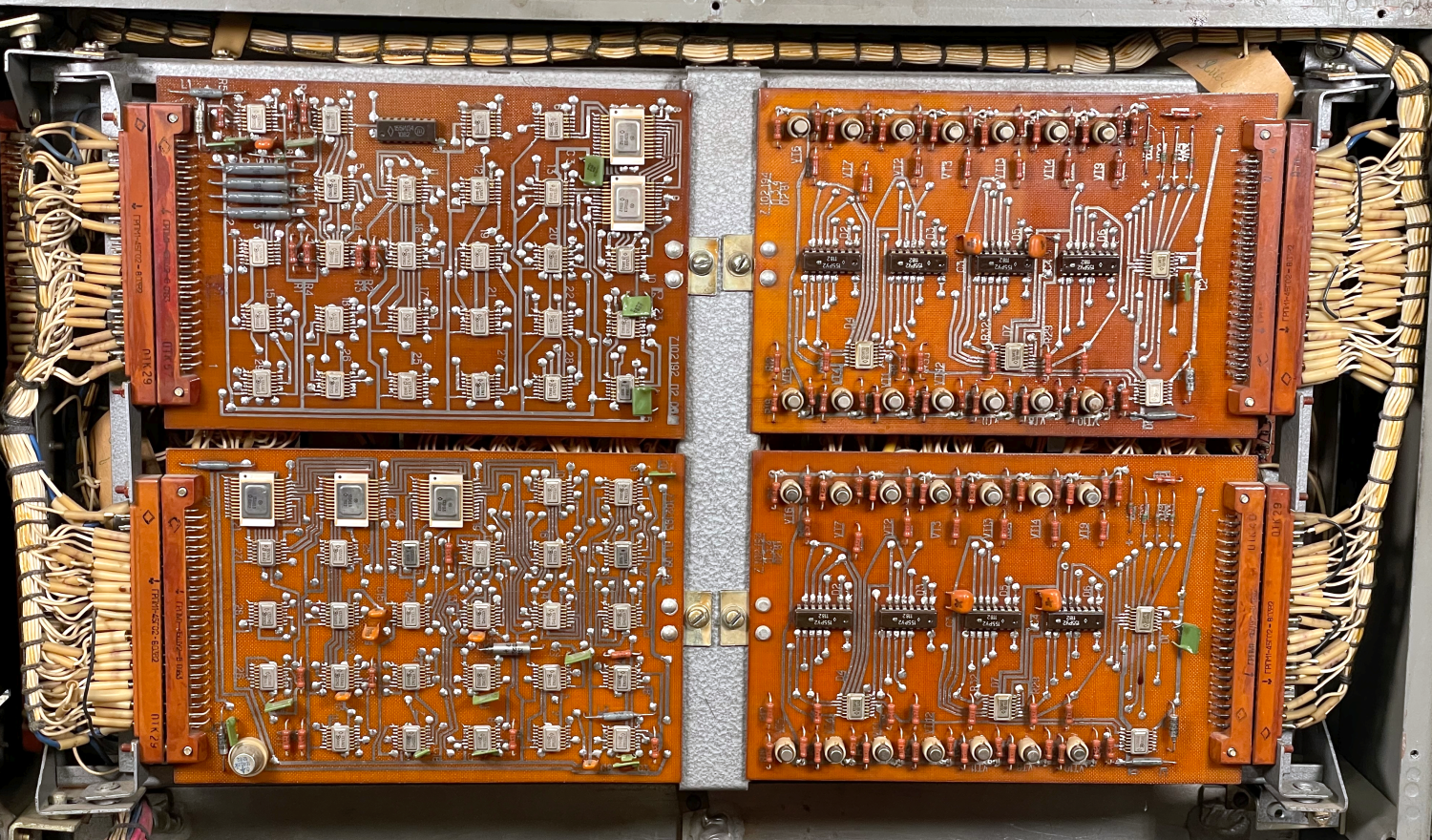
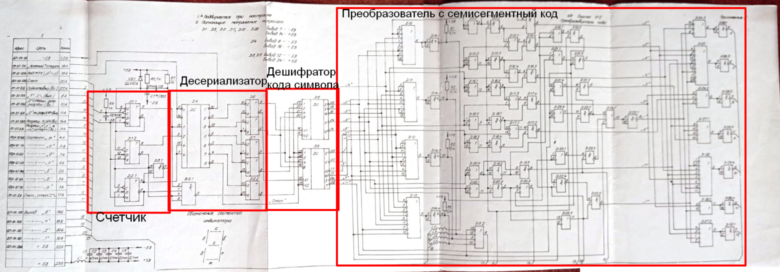
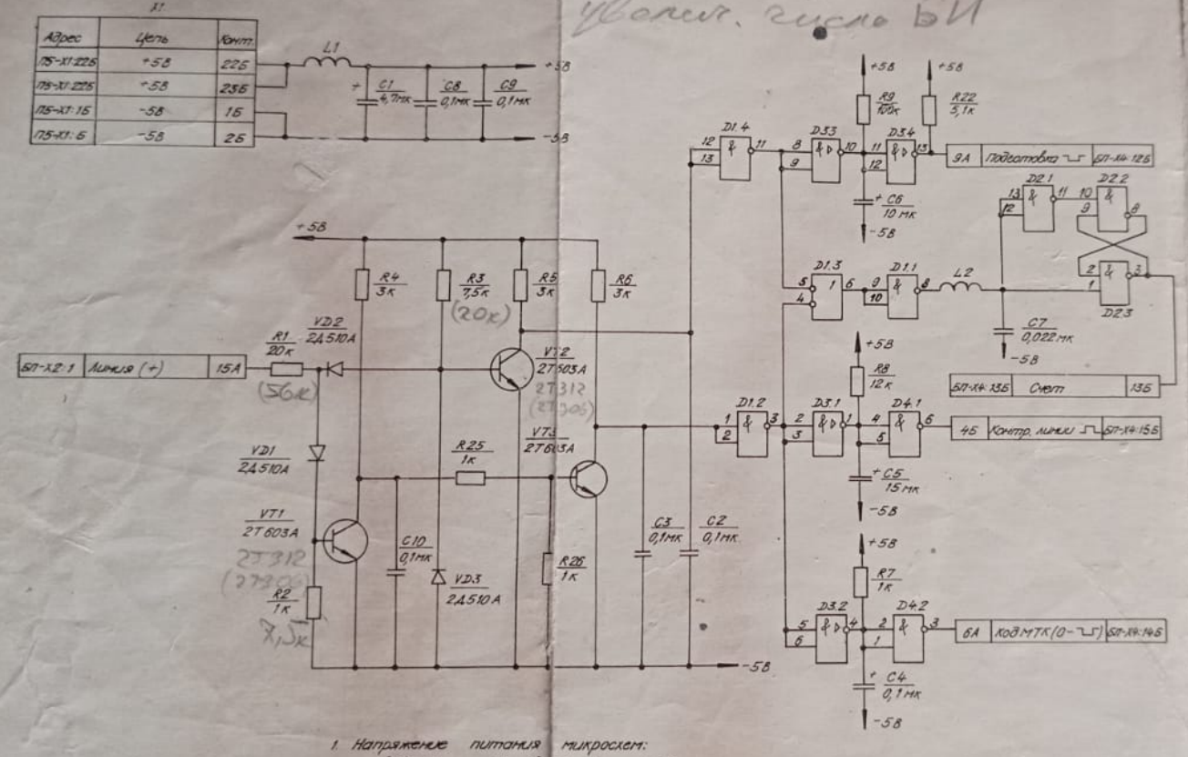
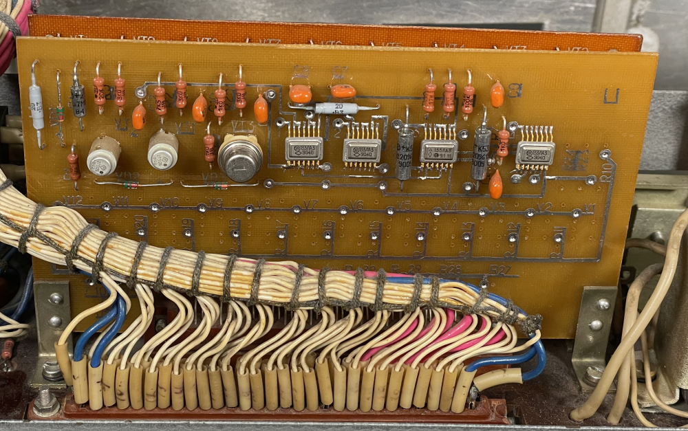
The device contains four circuit boards: two identical RAM boards for display storage, and two boards for code conversion and control logic, built with Soviet 133-series microchips.
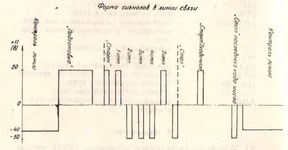
Signal Protocol
Data arrives sequentially as 47-character messages. Each character uses 5-bit encoding with start and stop pulses. Signal amplitude is plus or minus 50V. The "Preparation" signal resets the indicator. In idle state, -40V indicates an active connection.
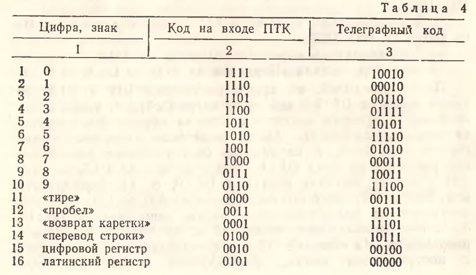
The indicator supports digits 0-9 and a minus sign "-" for blanking. Negative temperatures display "1" instead of "-". The protocol includes error protection through parity checking.
Signal sequence description:
- Preparation: Default high; pulses low briefly before data transmission to reset internal latches
- Line Control: Must be low when data is not transmitting; held high during transmission; controls response to zero-code transmission
- Clock: Strobes high during data transmission
- Code 0: Normally high; pulses low when transmitting zero bits; must occur after clock signal
Implementation Strategy
I chose to replace the original interface board with an ESP32-CAM module instead of building an external plus/minus 50V driver circuit. This allows autonomous operation while simplifying signal conversion from 3.3V to 5V using transistor inverters and K155LA3 logic gates.
Signal Transmission Code
Transmitting bits:
send_one(): Clock pulse high for 2 time units, low for 1 unitsend_zero(): Clock high with Code 0 low, then both return to rest state
Initial DELAY_US constant was 1000 microseconds. After debugging, it was reduced to 20 microseconds, achieving 25 ms total transmission time.
Character transmission sends a start bit (1), then 5 data bits (MSB first), then a stop bit (0).
Complete message transmission: sends a preparation signal (Preparation pulses low, Code 0 high), followed by all 47 characters with line control active, then deactivates the line.
Fetching Weather Data
The code requests METAR messages from NOAA (tgftp.nws.noaa.gov) or Aviation Weather (aviationweather.gov) services.
Two C++ METAR parsing libraries were evaluated:
- metaf: Feature-rich, template-based, single header file; compiled size approximately 1 MB (too large for ESP32)
- metar: Less complete but smaller; successfully fits on ESP32
Data Structure
A 47-byte message structure maps METAR fields to display positions, including temperature, wind direction and speed, pressure (millibars and mmHg), visibility distances, cloud height, and various weather indicators.
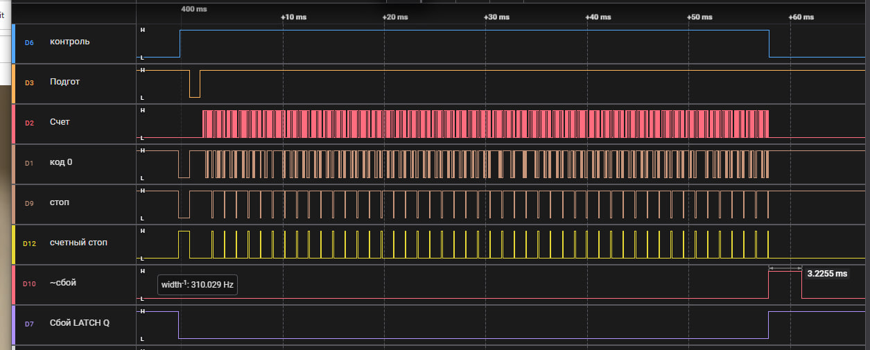
Debugging and Troubleshooting
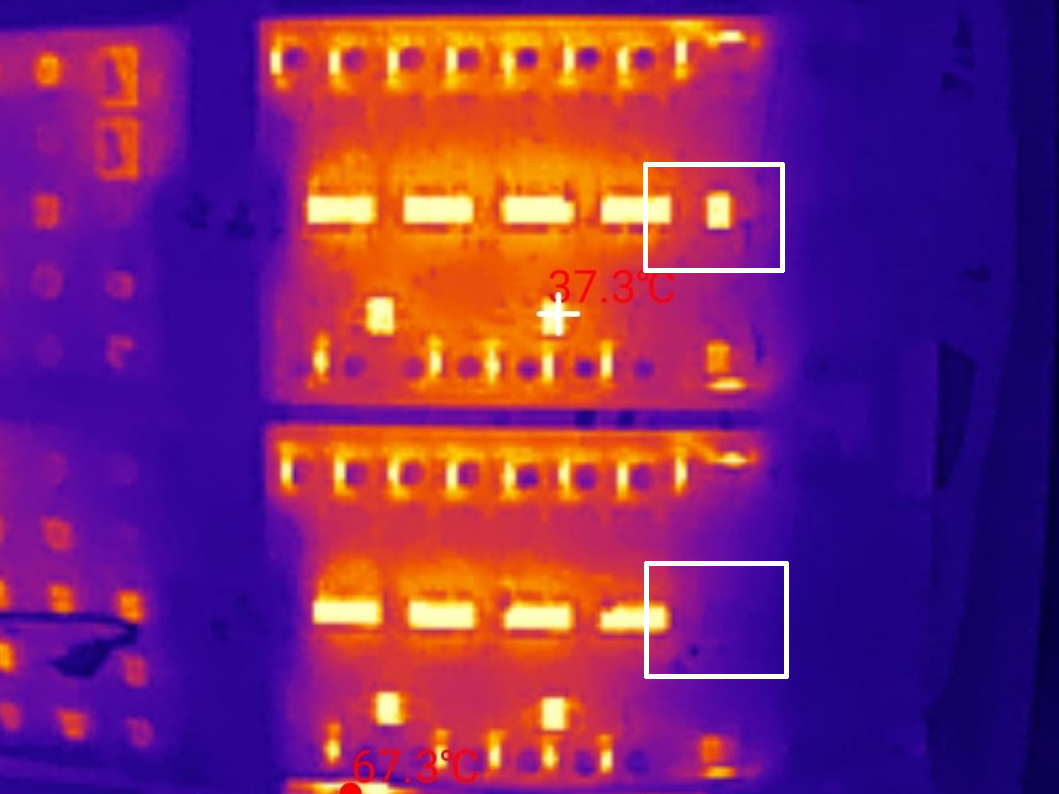
Initial testing showed the display flashing then going to blackout. Using a logic analyzer revealed a "fault" signal appearing 3 ms after transmission completion, blocking operation. Thermal imaging identified a defective parity check IC on the RAM board. Since the replacement chip K133IP2 was unavailable, the parity check was disabled, and the device functioned properly.
Final Implementation
A web interface was added for airport selection and configuration. It uses the ArduinoJson and ESPAsyncWebServer libraries. Configuration handlers load and save airport ICAO codes to the filesystem.
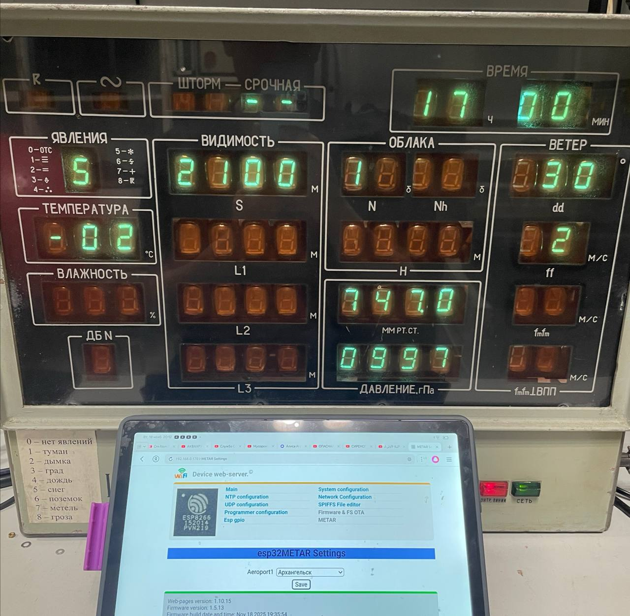
The device now autonomously fetches METAR data, allows airport selection via a web interface, and displays current meteorological conditions on the vintage 56-digit vacuum fluorescent indicator panel.