Extending the Life of a Haier TV Matrix After It Fails
A hands-on experiment to restore a Haier 58 Smart TV MX with a failed display matrix by isolating damaged driver contacts on the T-CON board, using a custom switching board with DIP switches to find the optimal pin configuration.
Greetings, !
Some modern frameless TVs have a problem with matrix failure. Anyone who has encountered this knows that replacing it is practically not cost-effective due to the high price. Sometimes it makes more sense to buy a new TV altogether. Problems vary, but there is one common issue that frequently occurs in newer Haier models.
Let me note right away that this is not about repairing a TV for resale, but rather an experiment that, as the title suggests, will extend the life of the matrix for some period. How long — that's unclear. There was a good YouTube channel where a service engineer mentioned several years of operation after a similar repair when a side driver failed.
Understanding What Happens to the Matrix
Let's try to understand what happens to a matrix that causes it to stop working. We won't consider the scenario where the screen was washed and water (or cleaning solution) got onto the flex cables, which then happily corroded and fell off. Our scenario is: the TV was working and, without any external influence, started showing static noise (there can be stripes, shaking, image doubling, etc.), when the problem is definitely in the matrix.
Previously, TV matrices had side "ears" with pixel driver ICs. They were called "TAB COF IC" and were hidden in the bezel around the screen.
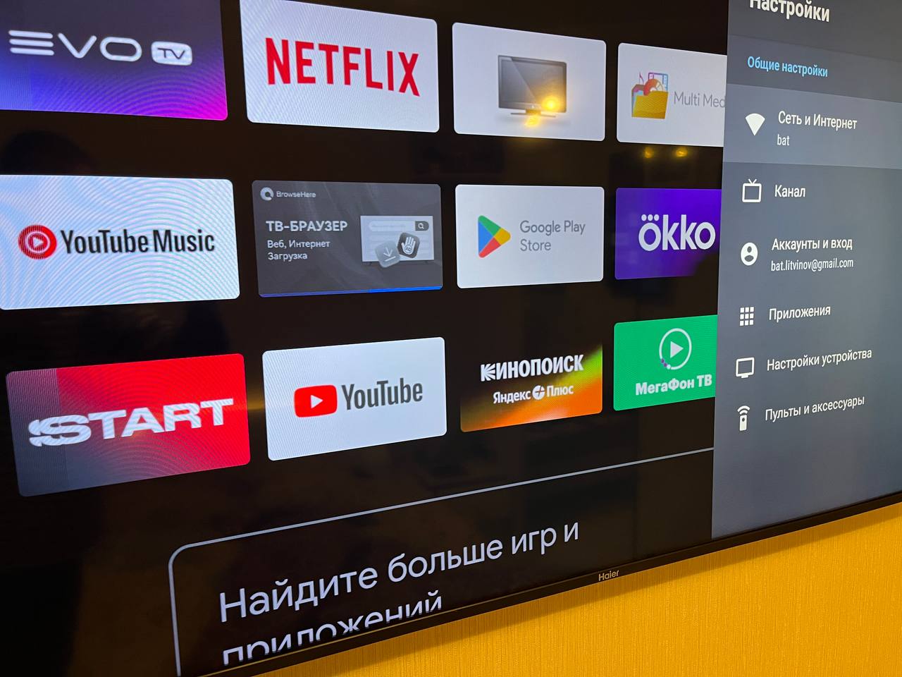
Fig. 1. TAB COF IC.
Such a driver could fail, for example, due to being torn from the glass during careless backlight replacement, or after moisture exposure. They also get punctured from overheating and possibly static. With the appropriate equipment and skills, they can be re-bonded with new ones (sold in rolls for specific panels). If anyone is interested in the topic of how matrices work, you can check the book by A.V. Samarin "Liquid Crystal Displays." It describes COF, COG, and TAB technologies in detail (others exist as well). We're interested in COG (Chip-on-Glass), where the control chip is integrated directly into the matrix glass. One of the main disadvantages of this method is its tendency to heat up, overheat, and ultimately fail.
The Patient: Haier 58 Smart TV MX
I received a Haier 58 Smart TV MX. First, image noise appeared, then after some time stripes developed. I got it in this condition:
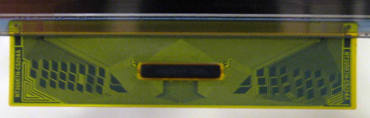
Fig. 2. Problem with the Haier 58 Smart TV MX.
From this image, you wouldn't even say that the matrix has failed. The image is static, there are no artifacts (except the stripe), and the picture is not visible. The quickest diagnosis for this problem is disconnecting one half of the matrix from the T-CON.
Fig. 3. T-CON CCPD-TC575-009.
The timing controller (T-CON) converts data from the MAIN board (LVDS) into signals that the matrix understands. If disconnecting one of the flex cables (on top) results in a full picture displayed on half the screen, then you're "lucky." Although, it depends on how you look at it. My problem turned out to be with the left half of the image.
The Repair Method
There is a fairly simple method that allows you to revive the matrix. Since a driver on the glass has been punctured, it needs to be isolated. First, I tried to detect the defect using a multimeter continuity test, measuring resistance on various contacts of the matrix ribbon connector (after disconnecting it from the T-CON) to identify a short circuit, but all to no avail. Voltage measurements also yielded no results — there were no drops when the faulty half of the matrix was connected.
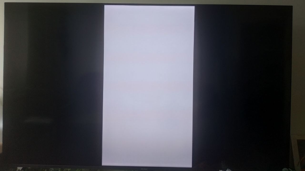
Fig. 4. Isolating several T-CON contacts.
Such manipulation inevitably leads to some image artifacts, for example the appearance of stripes (sometimes barely noticeable), formation of new image trails, or color imbalance — which is exactly what happened in my case.
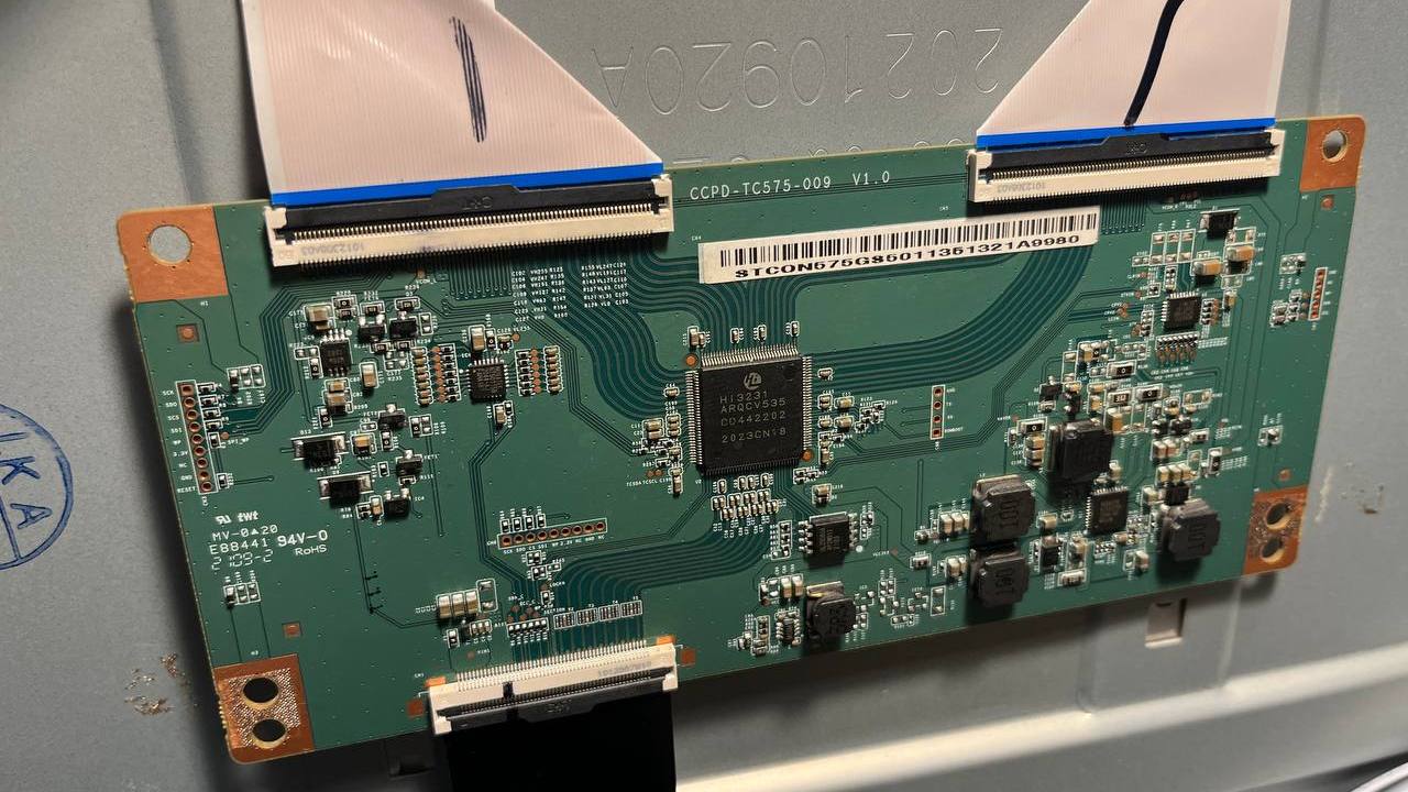
Fig. 5. White color shifting to pink.
In principle, the picture was restored, but on the left part of the image there is a clear shift of white toward pink. As you move closer to the center of the screen, the effect gradually disappears. So here I was unlucky — something needed to be done about the color.
On the internet you can find plenty of information about how to properly isolate contacts, adjusting the width of tape strips, moving them and splitting them into parts, but each "extra" isolated contact leads to worse picture quality. I went a bit further and decided to make a board that would allow me to disconnect contacts, achieving optimal image quality.
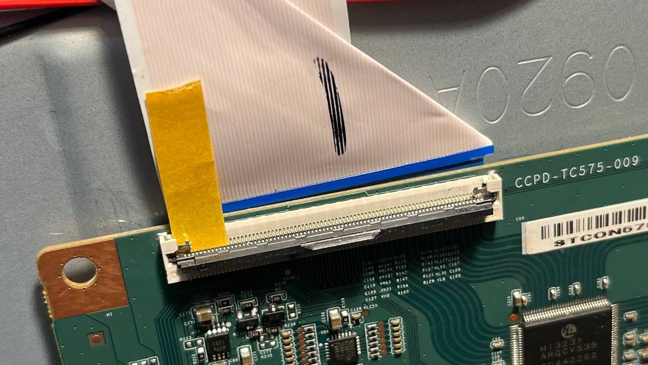
Fig. 6. Switching board.
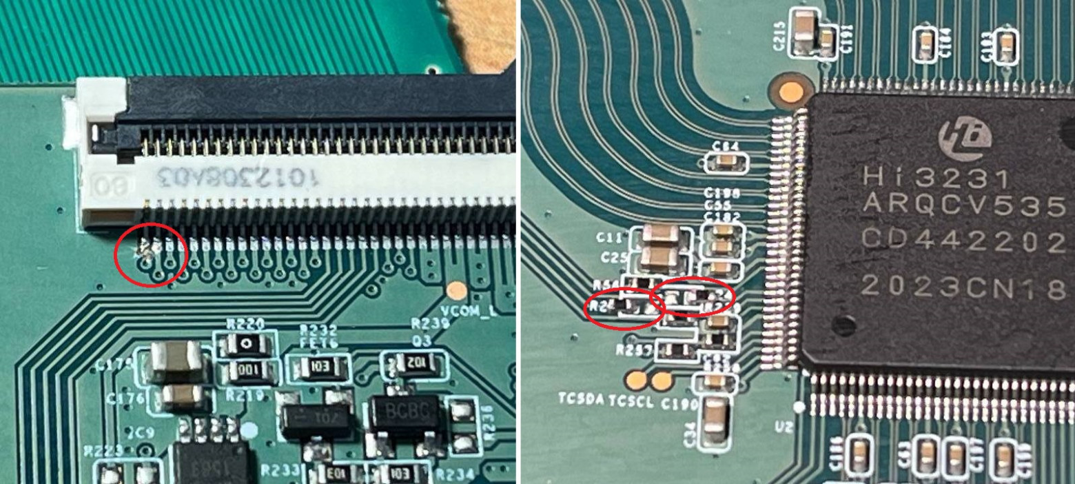
I made it possible to disconnect the first 47 pins (here and below I count from the left) using DIP switches. By my estimates, only 15-20 would be significant for this operation, but everything is ambiguous since there is no datasheet for the T-CON. After several experiments, it became clear that the pink-tinted picture results from isolating only the first pin, which goes to the glass voltage generation IC NT50149E — and this is the VGH signal.
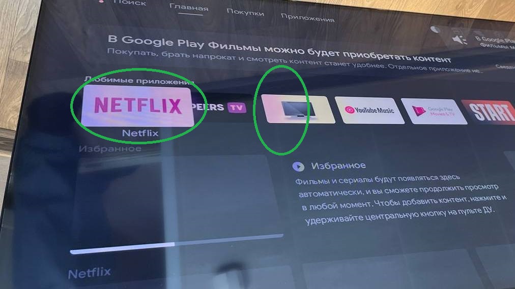
Fig. 7. VGH resistor on NT50149E.
Trying to remove the resistor didn't help. The picture didn't appear on either half, since the VGH signal goes to both T-CON connectors. I put the resistor back. I take VGH measurements on the right and left parts again — no result, which is strange. I keep looking.
To get rid of the pink color, I had to "disconnect" two more pins (21 and 22). They go to the Hi3231 processor (T-CON). When disconnecting these signals from the left half, the following picture was observed:
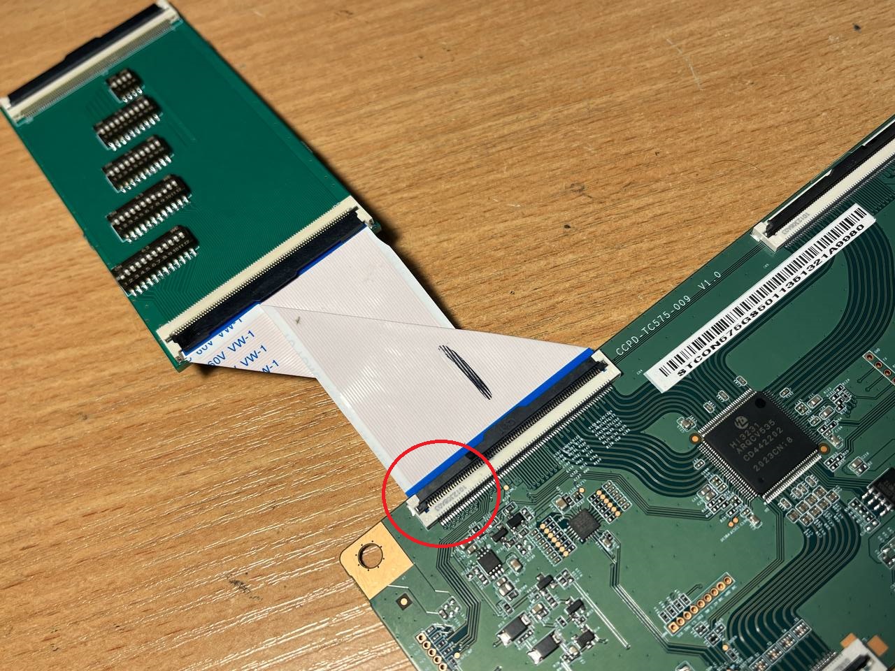
Fig. 8. Picture with pins 21 and 22 disconnected from the left half of the matrix.
All colors are normal, but black has become more gray at the image boundary. Although black itself is also fully present on the left. For example, when navigating through the menu, at some point the background becomes uniformly black; when returning to the previous menu, the separation appears again. Below is a picture from a different menu:
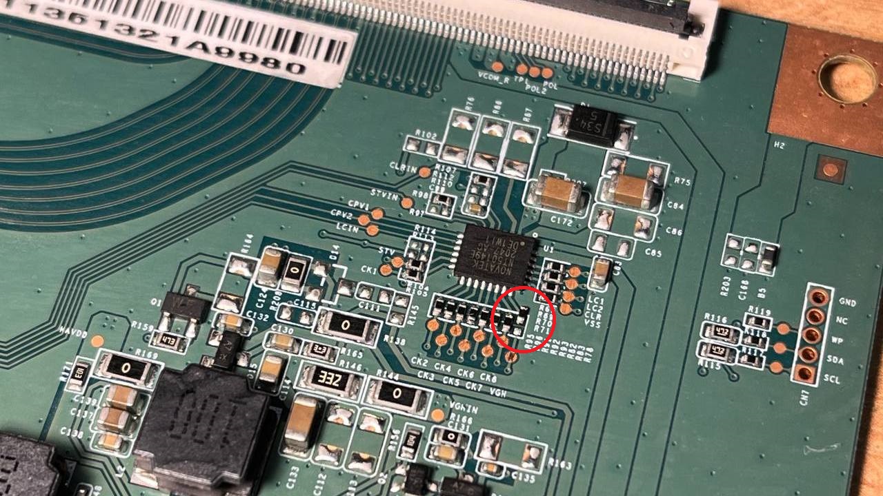
Fig. 9. Picture with pins 21 and 22 disconnected in another menu.
This result seemed the most acceptable to me. I remove the board with DIP switches and cut the VGH trace for the left half on the T-CON side. To make the right and left halves identical, I desolder two resistors from the Hi3231 processor (these pins are connected on the right and left connectors).
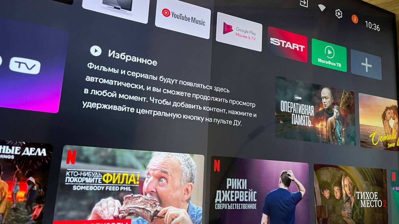
Fig. 10. Disconnecting pins 1, 21, and 22.
You can't exactly call this a TV repair. Although its operability has been restored, I couldn't come up with anything better short of replacing the entire matrix. At this point, I've done a two-hour burn-in test, held it on a static image for a while, and watched a couple of movies. Everything is running smoothly.
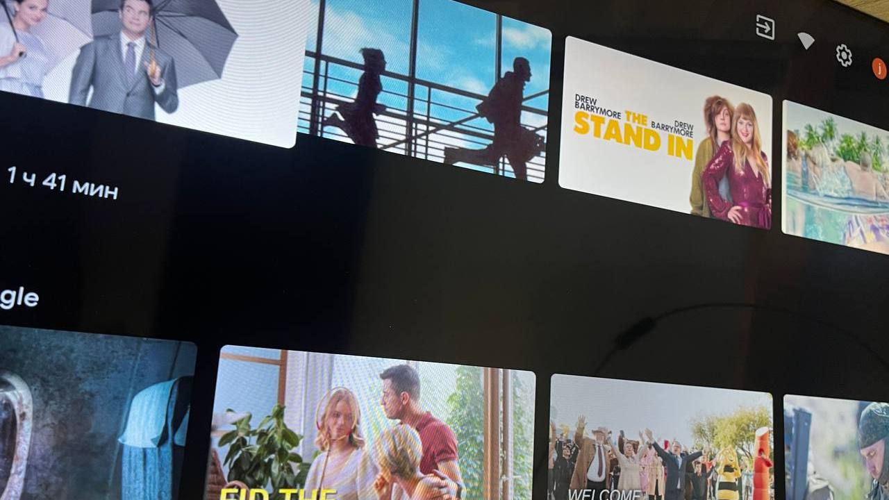
Fig. 11. Final image without artifacts.
P.S: In some photos you can see radial stripes on the image, but these are not artifacts — they result from photographing the TV screen with a smartphone.
Thanks for reading, and good luck!
FAQ
What is this article about in one sentence?
This article explains the core idea in practical terms and focuses on what you can apply in real work.
Who is this article for?
It is written for engineers, technical leaders, and curious readers who want a clear, implementation-focused explanation.
What should I read next?
Use the related articles below to continue with closely connected topics and concrete examples.