Emulating the 90s Apollo Tetris and Running Code on Original Hardware
A deep dive into reverse-engineering 1990s Apollo handheld game consoles based on Sunplus microcontrollers, building an emulator, exploiting a debug mode to run custom code on original hardware, and playing Bad Apple on a 40-segment LCD.
This article continues a series of publications about electronic portable games from the 90s and their microcontrollers. This time we'll look at the Sunplus family of microcontrollers SPL02/SPL03, which were used in popular Apollo gaming devices.
Apollo 126 in 1 (B0202)
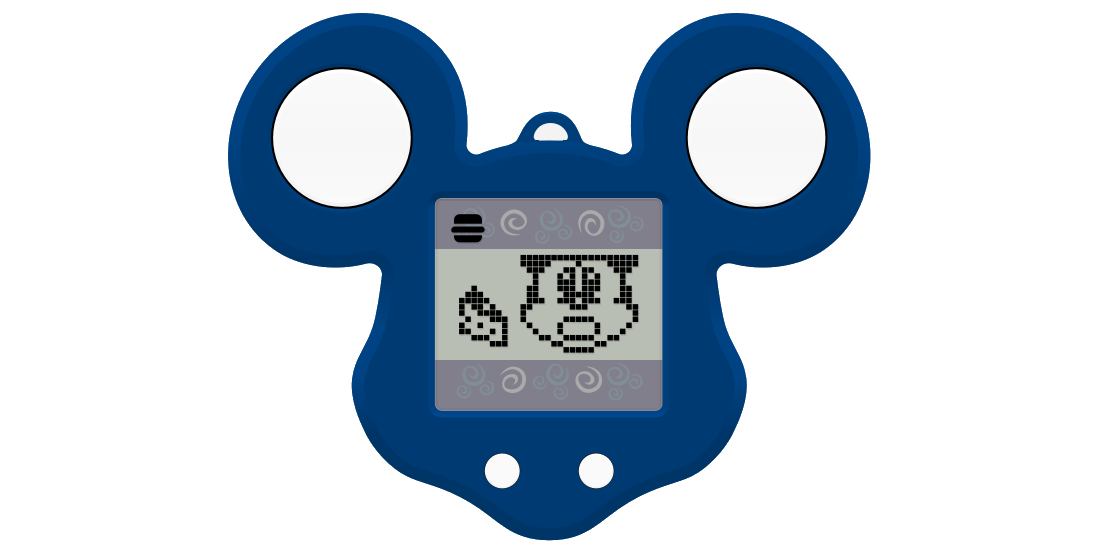
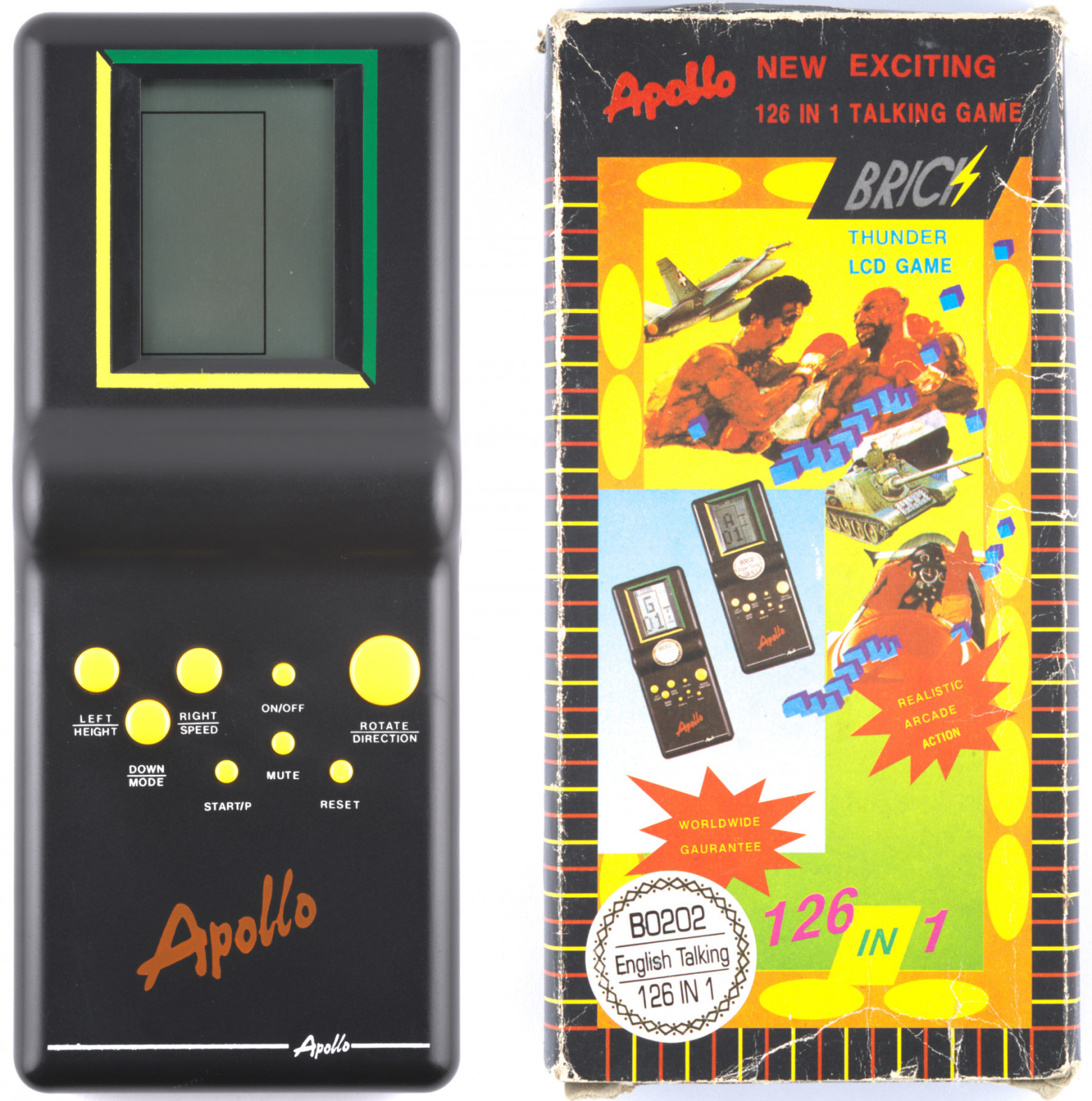
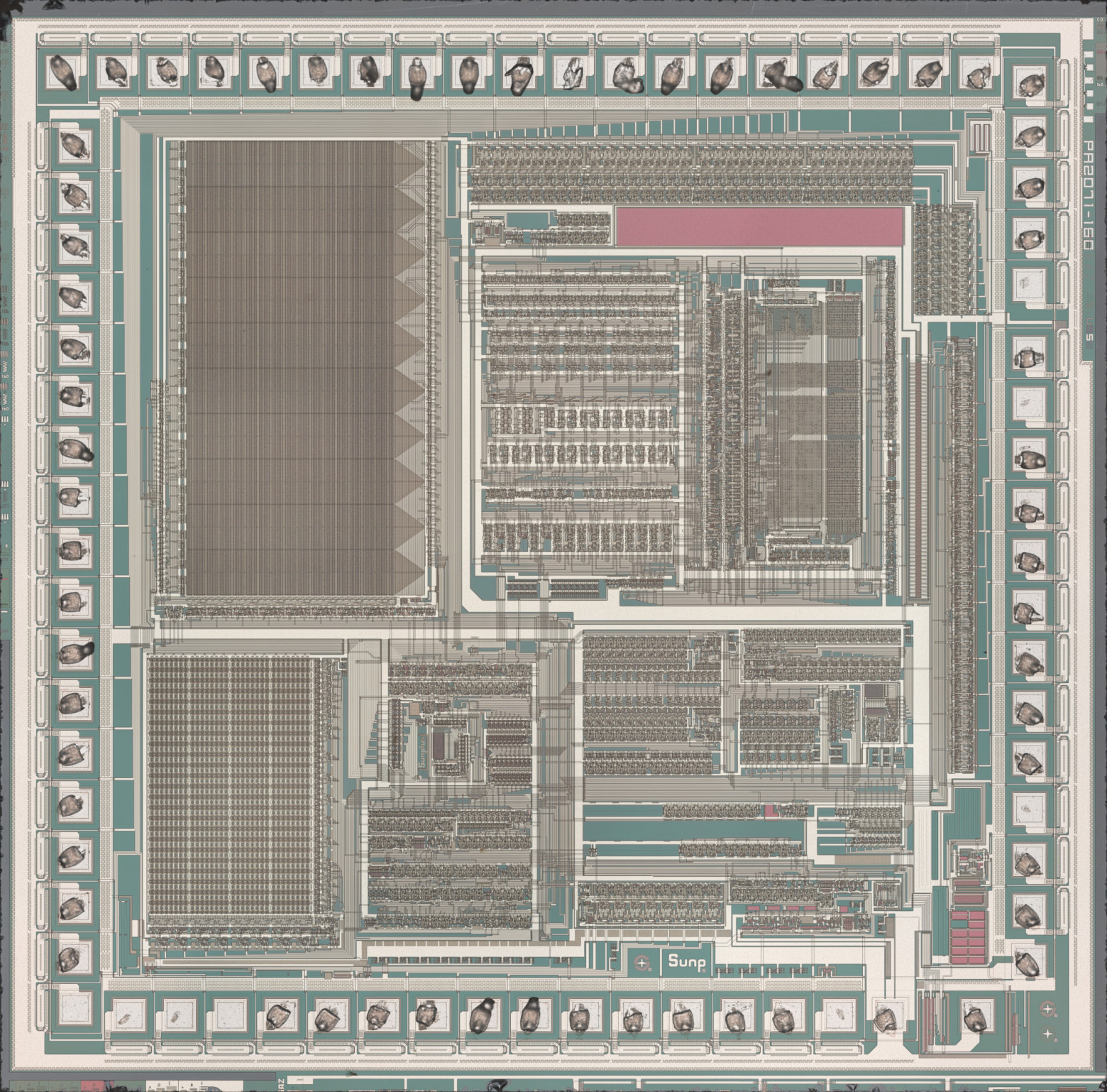
The device was released in April 1995 and contains a Sunplus PA2071-160 microcontroller. Key specifications:
- Processor: 8-bit 6502 core (modified version)
- ROM: 19.5 KB
- RAM: 192 bytes
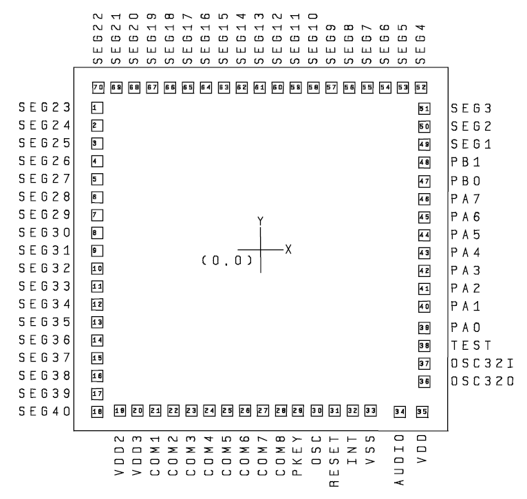
- LCD driver: 40 segments, 8 common pins
- Sound: 7-bit DAC with two tone channels, a noise channel, and a speech channel
The device stands out with voice commentary accompanying the gameplay.
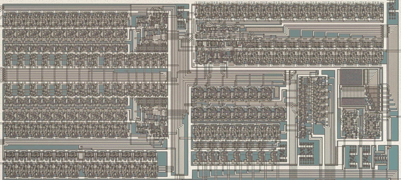
Technical Research
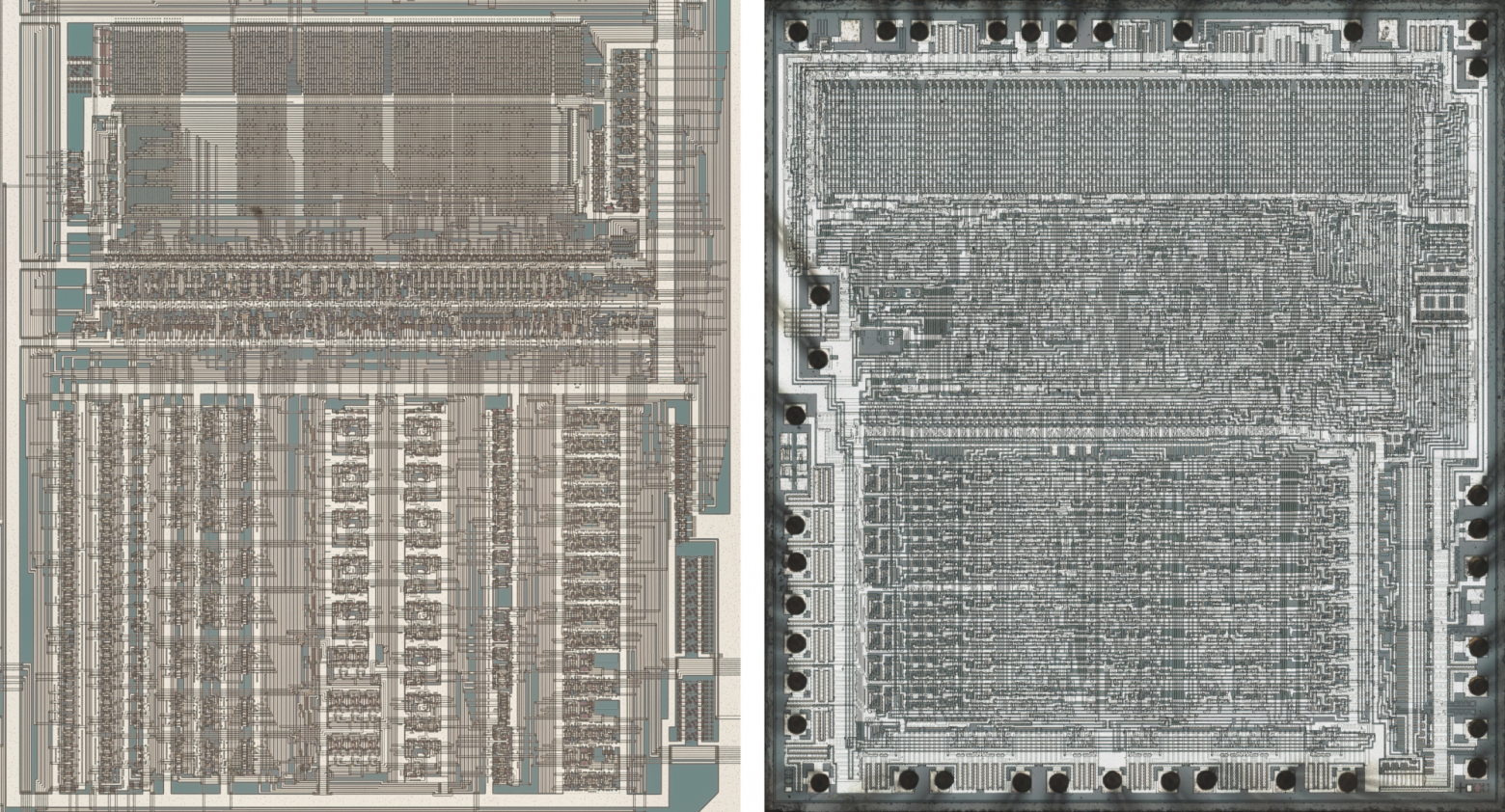
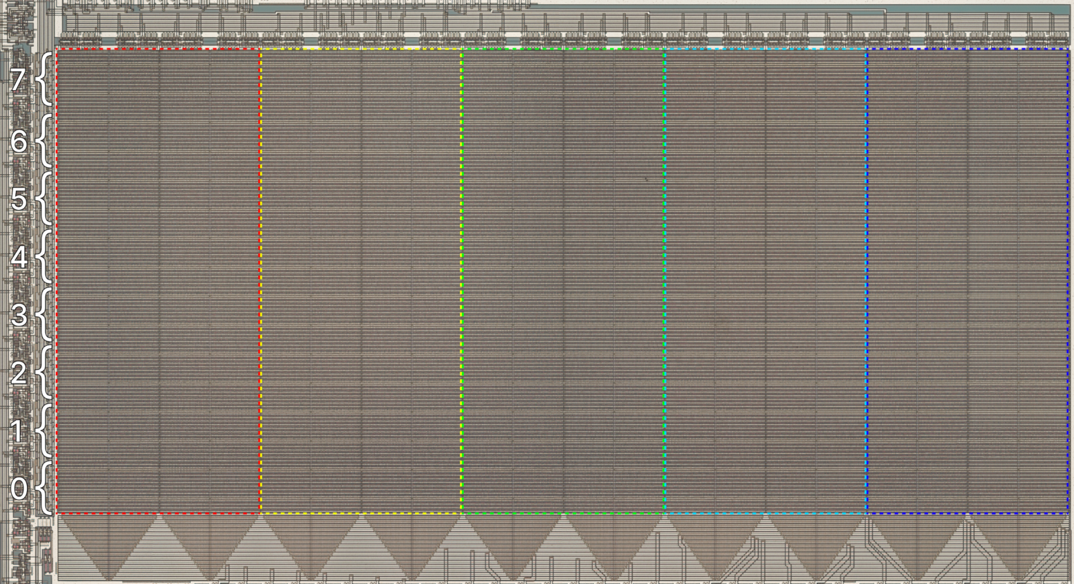
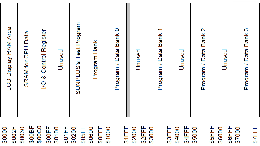
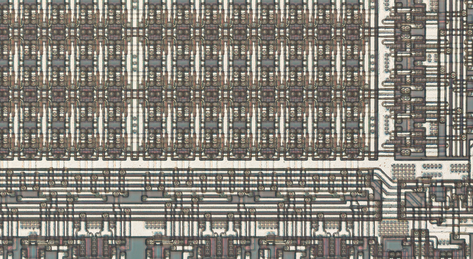
Memory Structure
The first 512 bytes of ROM are physically present on the die but are not addressable. Video memory occupies 48 bytes (6 bytes for each of the 8 common pins); each bit controls one segment.
Sound System
Speech phrases are stored in 4-bit PCM format (two samples per byte), table-stretched to a 7-bit range, and played back at approximately 6 kHz. A half-second utterance of the word "Apollo" occupies 1,406 bytes.
Emulation
The author developed BrickEmuPy — an emulator supporting 11 microcontroller families and about 50 games. SPL02 became one of the added families.
Running External Code
A debug mode routine was discovered in the firmware that reads 120 bytes from the ports and executes them as code. An external interrupt is used for activation.
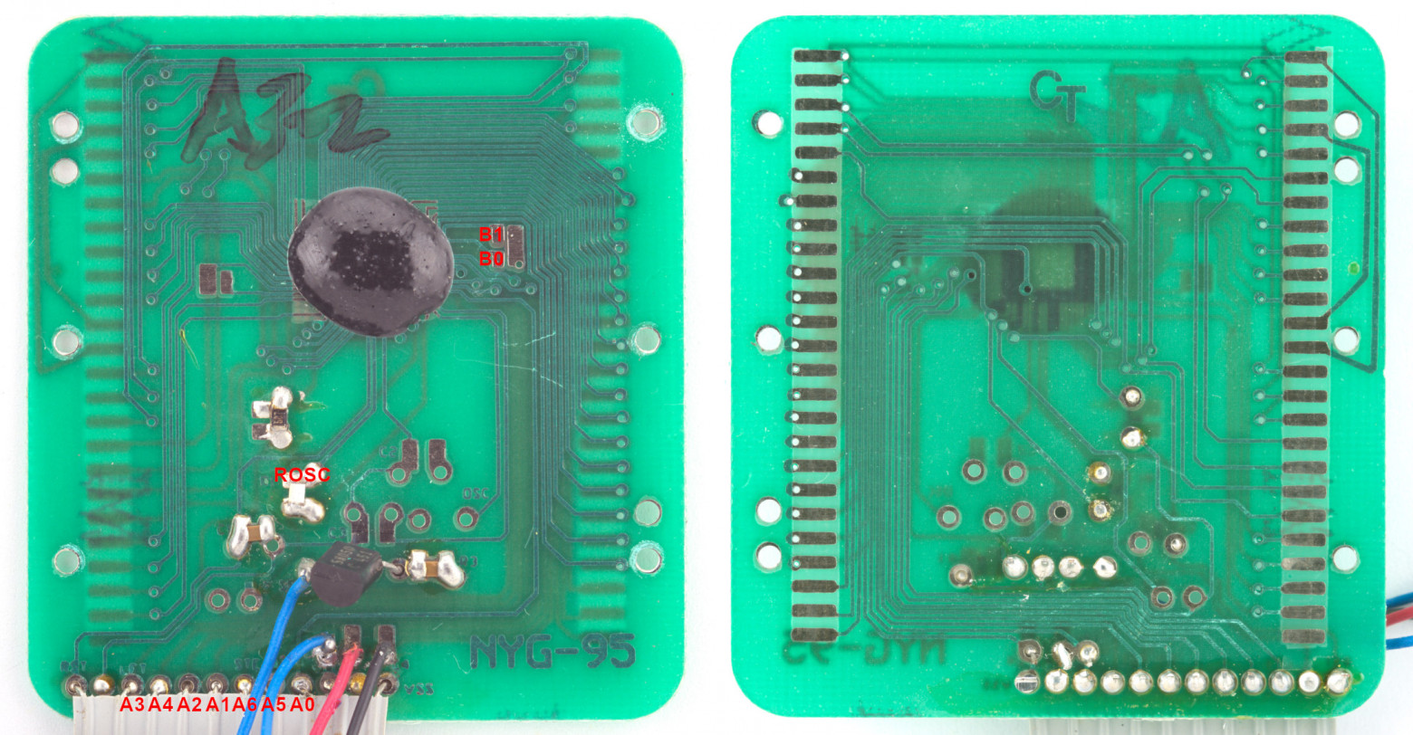
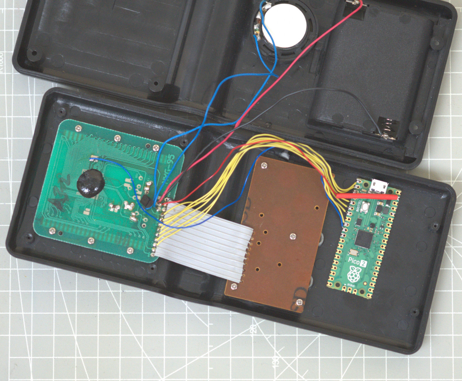
Experimental Setup

On the B0302 model (18 in 1), the author was able to trigger the debug mode via electromagnetic interference on the frequency-setting resistor. A Raspberry Pi Pico 2 was used to automate data transfer.
Solving the Bit Problem
Port A outputs only the 7 least significant bits. To transmit full 8-bit instructions, a scheme with correcting code was implemented:
0000: sec
0001: rol $03
0003: .byte $54, $00
After executing the first instructions, $54 00 is transformed into $A9 00 (lda #0).
Bad Apple!! Player
A demonstration project playing video on a 40-segment LCD display:
- Video stream: 21 frames/sec (interpolation of original 30 frames)
- Audio stream: 5-bit PCM, ~22 kHz
- Synchronization: 42 frames/sec display refresh
Each transmitted byte contains a 5-bit audio sample and 1 bit of segment state. Processing one byte takes exactly 32 processor cycles.
B0302 Specifications
During the research, it was found that the B0302 uses an SPL03 microcontroller:
- ROM: 11.5 KB (two banks of 5.75 KB)
- RAM: 128 bytes
- Sound: 5-bit PWM (instead of 7-bit DAC)
Code is loaded from address $0000 (not $0038 as in B0202).
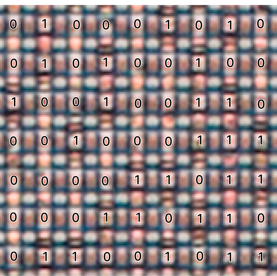
Reading the Firmware
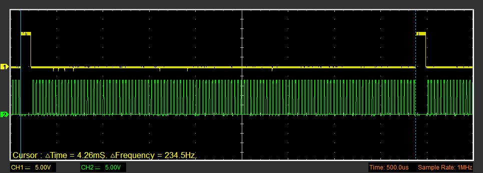
A program was implemented for the B0302 that transmits ROM contents via Port B bit by bit. Data is read by a logic analyzer, eliminating the need for decapsulation and photomicroscopy.
Available Resources
All source code is published on GitHub, and photos and materials on the Apollo B0202 are hosted on archive.org.


