A DIY Battery Capacity Tester for the People
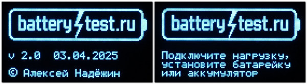
Alexey Nadezhin presents BatteryTest 2, a DIY device for measuring battery and accumulator capacity with four-wire connection, MicroSD logging, and support for everything from watch cells to car batteries.
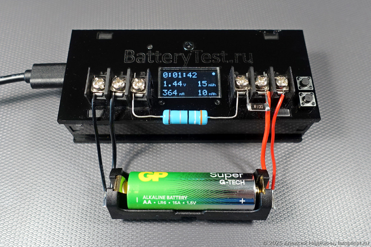
I have completed work on the second version of BatteryTest — a device for measuring battery and accumulator capacity. It is simple, accurate, and universal: it can test everything from watch batteries to automotive accumulators.
Key Improvements in Version 2
The new version introduces several enhancements over the original:
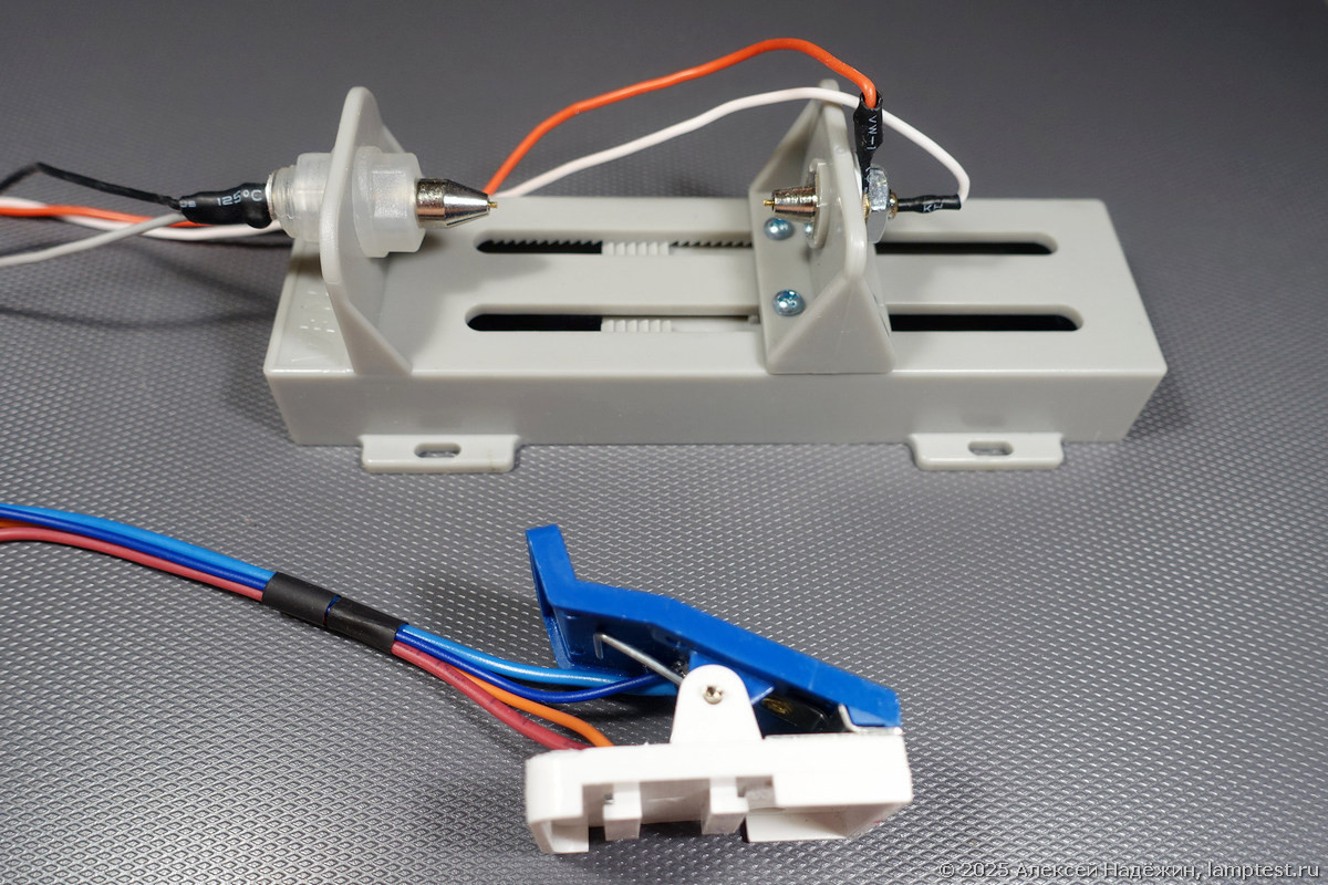
- Four-wire connection for improved measurement accuracy at high currents
- Voltage and current calibration stored in flash memory
- MicroSD card data logging
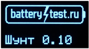
- Four measurement shunt ranges (0.08–8 mA, 0.8–80 mA, 8–800 mA, 0.08–8 A)
- Manual adjustment of the test end voltage threshold
- Load disconnect capability for accumulators
- Previous test result storage with resume functionality
- Excel-compatible tab-separated data format
- Multimeter mode for voltage and current measurement
- Modular construction — install only the components you need
Technical Specifications
Measurement capabilities:
- Voltage range: 0.5–36 V
- Current range: 0.1 mA to 8 A (depends on shunt selection)
- Capacity measurement: 1 to 99,999 mAh
- Energy measurement: 1 to 99,999 mWh
- Test duration: 10 seconds to 1,000 hours
Core hardware components:
- Microcontroller: D1 mini (ESP8266-based)
- Display: 0.96" OLED screen
- Measurement module: Texas Instruments INA226 (±0.15% measurement accuracy)
- Terminal blocks for connections
Practical Resistor Values for Common Battery Types
The load resistor determines the discharge current. Here are recommended values for common battery types:
- 12 Ohm: AA/AAA batteries at maximum capacity extraction (75–130 mA)
- 3.9 Ohm: AA batteries at elevated load (230–410 mA)
- 5.1 Ohm: AAA batteries at elevated load, or NiMH accumulators
- 1 kOhm: CR2032 coin cells (2–3 mA)
Load resistors must have substantial power ratings to prevent overheating during extended tests.
Operating Modes
The device features several operating modes:
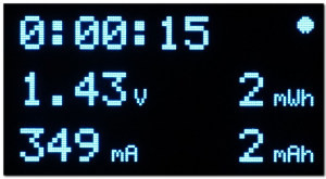
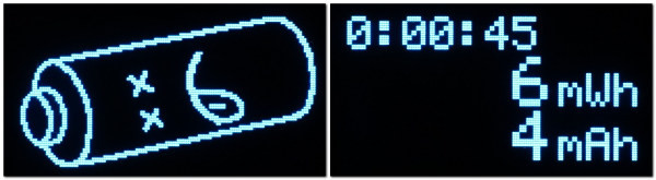
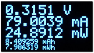
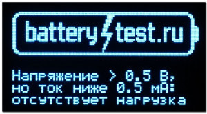
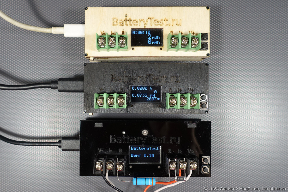
Test Mode: Displays real-time voltage, current, accumulated energy (mWh), and charge (mAh). The screen shows all four values simultaneously, updating every second. When the battery voltage drops below the cutoff threshold, the test ends and the final results are displayed.
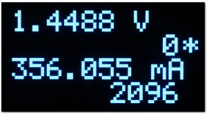
Multimeter Mode: Measures voltage, current, and power in real time. Useful for checking power supplies, measuring standby current, and general bench work.
Calibration Mode: Allows independent calibration of voltage and current measurements for each shunt nominal value. Calibration data is stored in flash memory and survives power cycles.
Automatic Cutoff Voltages
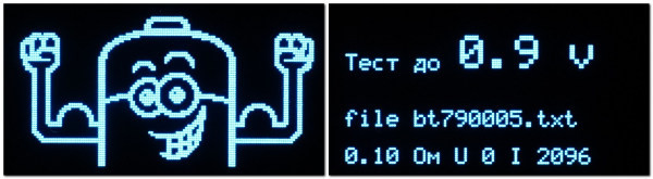
The device automatically sets discharge endpoint voltages based on the initial battery voltage:
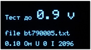
- Batteries under 2 V: cutoff at 0.9 V (single-cell alkaline/zinc)
- CR2032 / CR123A type: cutoff at 2.0 V
- Single lithium accumulators: cutoff at 2.5 V
- Multi-cell lithium configurations: 5.0 V, 7.5 V, 10.0 V, up to 20 V depending on detected cell count
The cutoff voltage can also be adjusted manually using the buttons.
Data Management
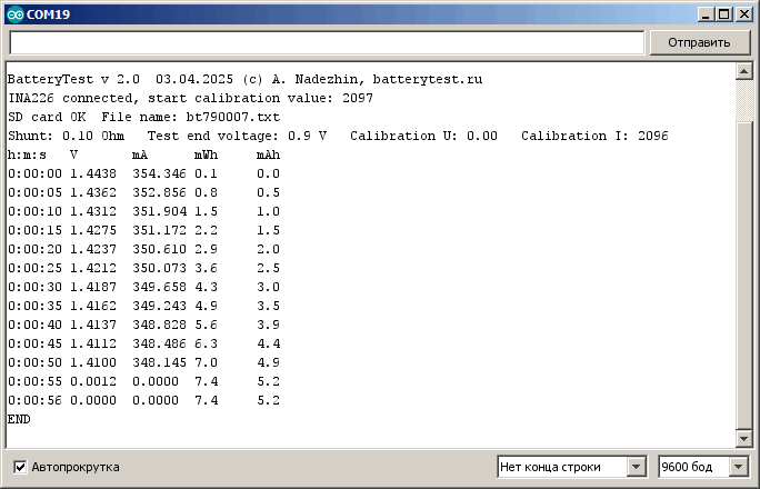
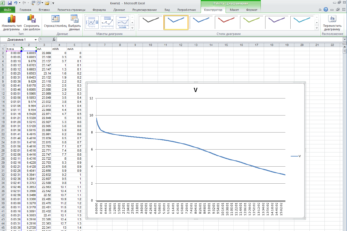
Test data is transmitted every 5 seconds via USB at 9600 baud and optionally saved to MicroSD card. The data uses a tab-separated format that can be directly imported into Excel. Simply copy the file from the card, open it in Excel, and you get voltage and current graphs over time.
Each device receives a random identifier (11–99) used for file naming on the MicroSD card, making it easy to distinguish data from multiple devices.
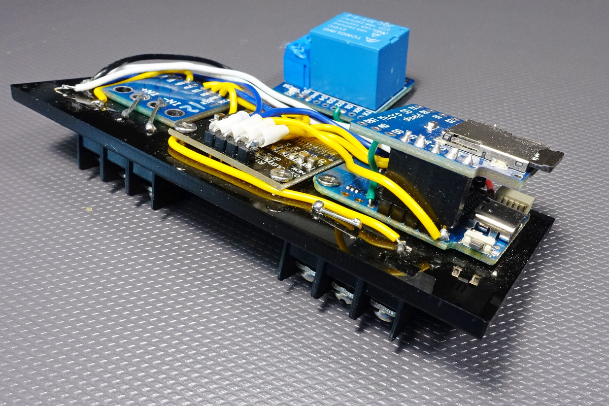
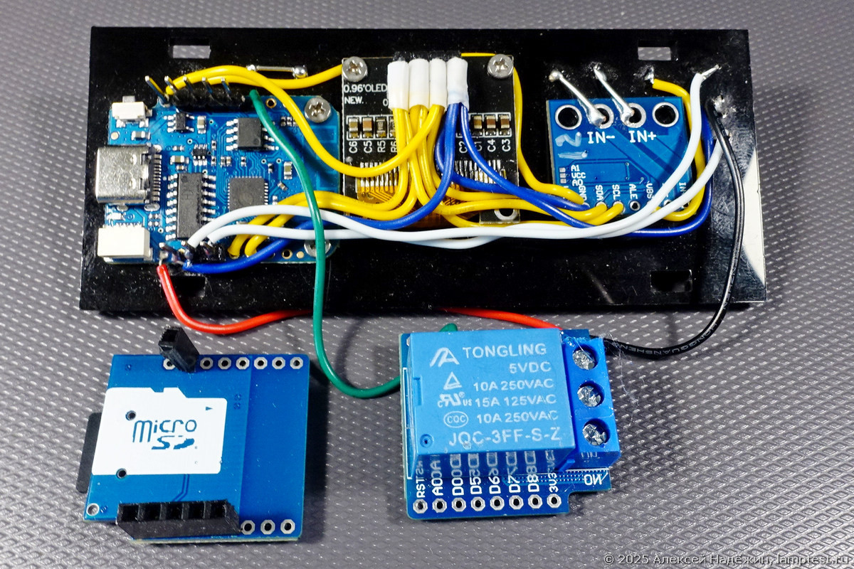
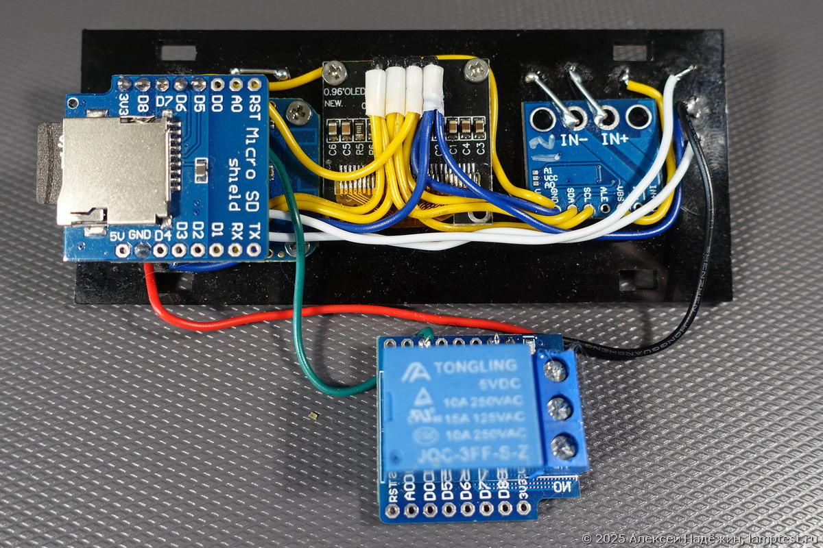
Circuit Architecture
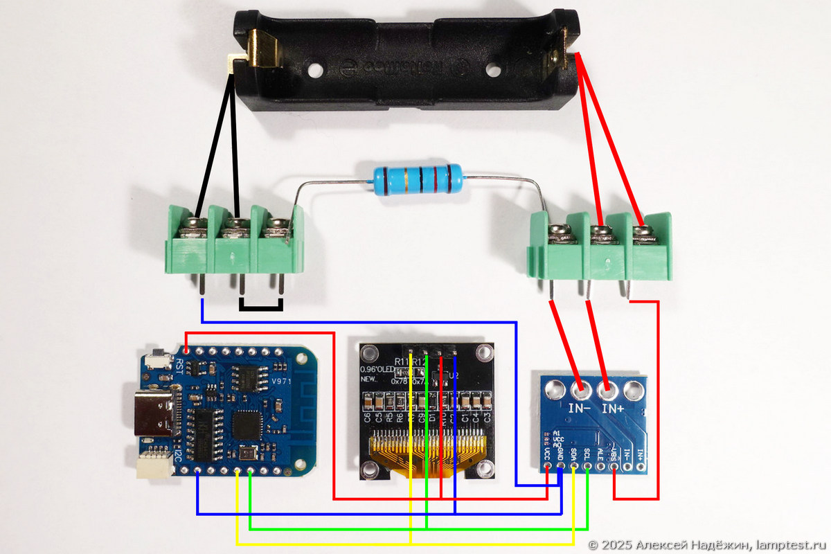
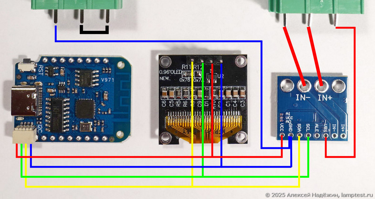
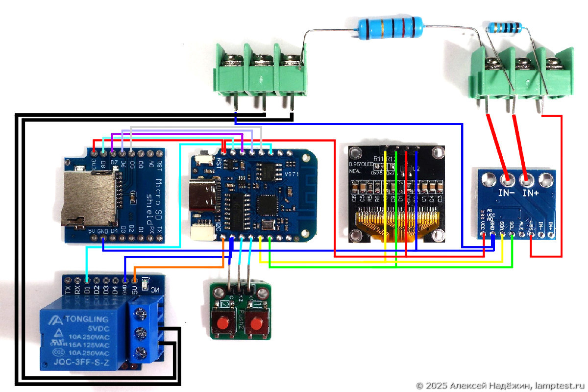
The minimal configuration requires just three modules: the microcontroller, OLED display, and INA226 measurement module. The maximum configuration adds buttons for control, a MicroSD module for data logging, and a relay module for load disconnect.
The design emphasizes modularity — you install only the components you need for your use case. Testing coin cells? Skip the relay module. Need data logging? Add the MicroSD card. The four-wire connection ensures accuracy even with long leads at high currents.
Power Consumption
- 25 mA without MicroSD card
- 40 mA with MicroSD card inserted
- 110 mA when the relay module is operating
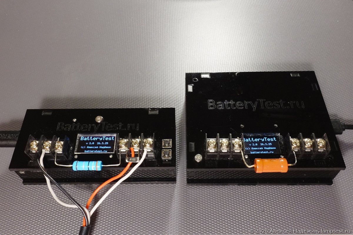
Assembly and Housing
The OLED screen mounts inverted for ergonomic convenience. The INA226 module is positioned close to the positive terminal block to minimize trace resistance. The MicroSD module stacks above the controller to save space.
I created enclosures from both acrylic and plywood. The plywood variant measures 99 x 40 x 26 mm. An enlarged version accommodates an 18650 accumulator, a charging circuit, and a voltage converter for fully autonomous portable operation.
Practical Application
BatteryTest 2 supports my battery testing project at Batterytest.ru and helps companies select battery suppliers without relying on expensive commercial laboratories. The device enables anyone — even non-technical users — to test batteries simply: connect the battery, wait for the test to complete, and read the results.
Firmware and Availability
The firmware, source code, and links to all required components are available at ammo1.ru/btest2. The software is free for private non-commercial use; modifications require the author's permission.
I plan to offer finished devices for commercial clients and component kits for individual builders who want to assemble their own.
FAQ
What is this article about in one sentence?
This article explains the core idea in practical terms and focuses on what you can apply in real work.
Who is this article for?
It is written for engineers, technical leaders, and curious readers who want a clear, implementation-focused explanation.
What should I read next?
Use the related articles below to continue with closely connected topics and concrete examples.