Burning and Flashing Controllers to Feed Nuclear Backlighting
A detailed engineering journey of building a custom addressable LED backlighting system for a three-monitor video wall with 2,315 pixels, covering power distribution, controller selection, custom WS2812b protocol implementation on STM32, and hard-won lessons about signal integrity and galvanic isolation.
Introduction
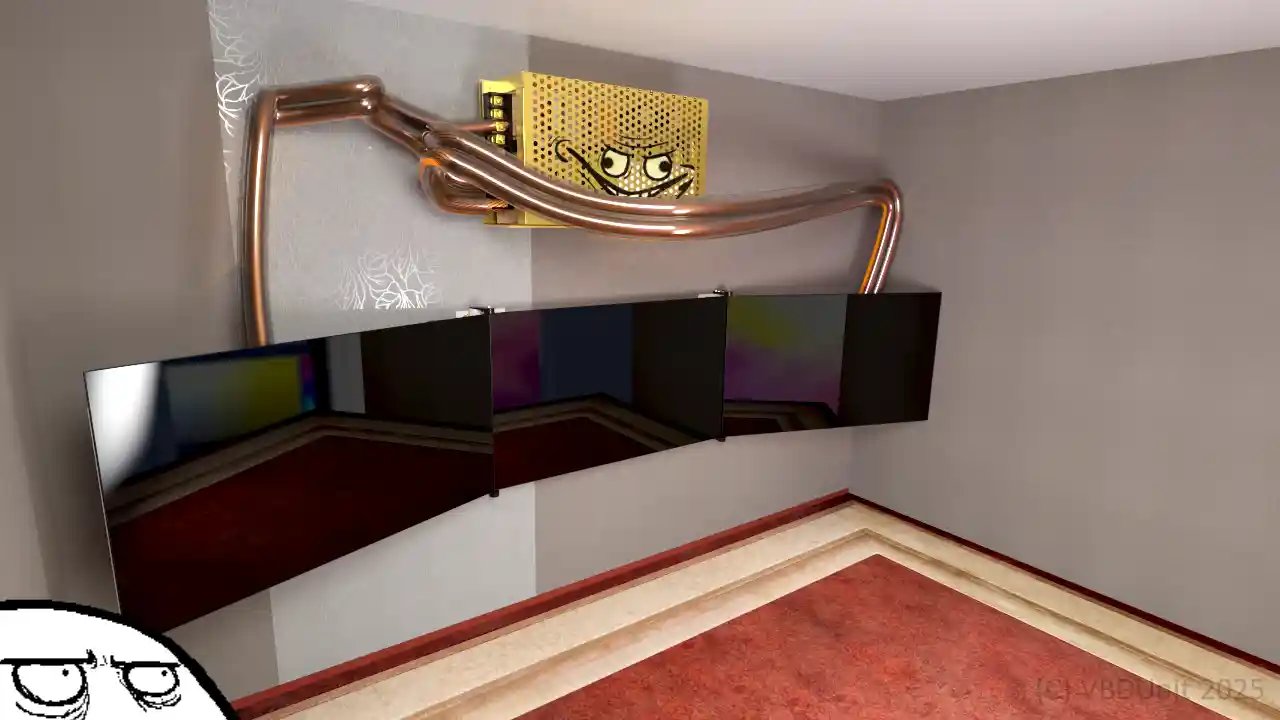
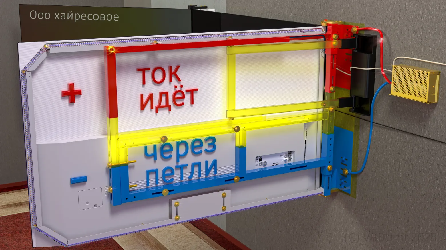
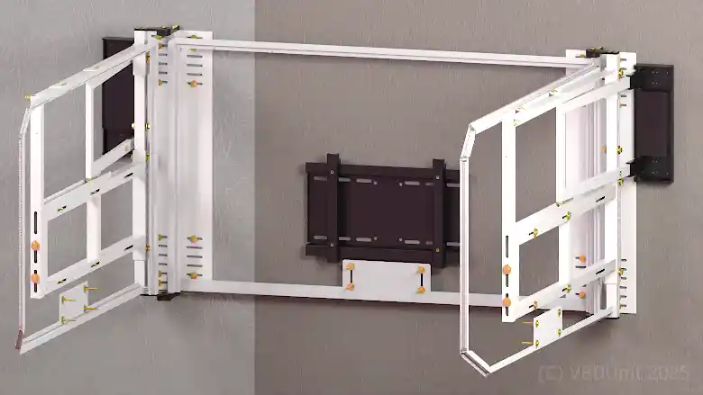
This is the story of building a custom LED backlighting system for a mechanical video wall made of three televisions. The system drives 2,315 addressable pixels, requires up to 90 amperes at 5 volts, and demanded solving a chain of increasingly difficult engineering problems — from power distribution to nanosecond-precision signal timing.
The Power System

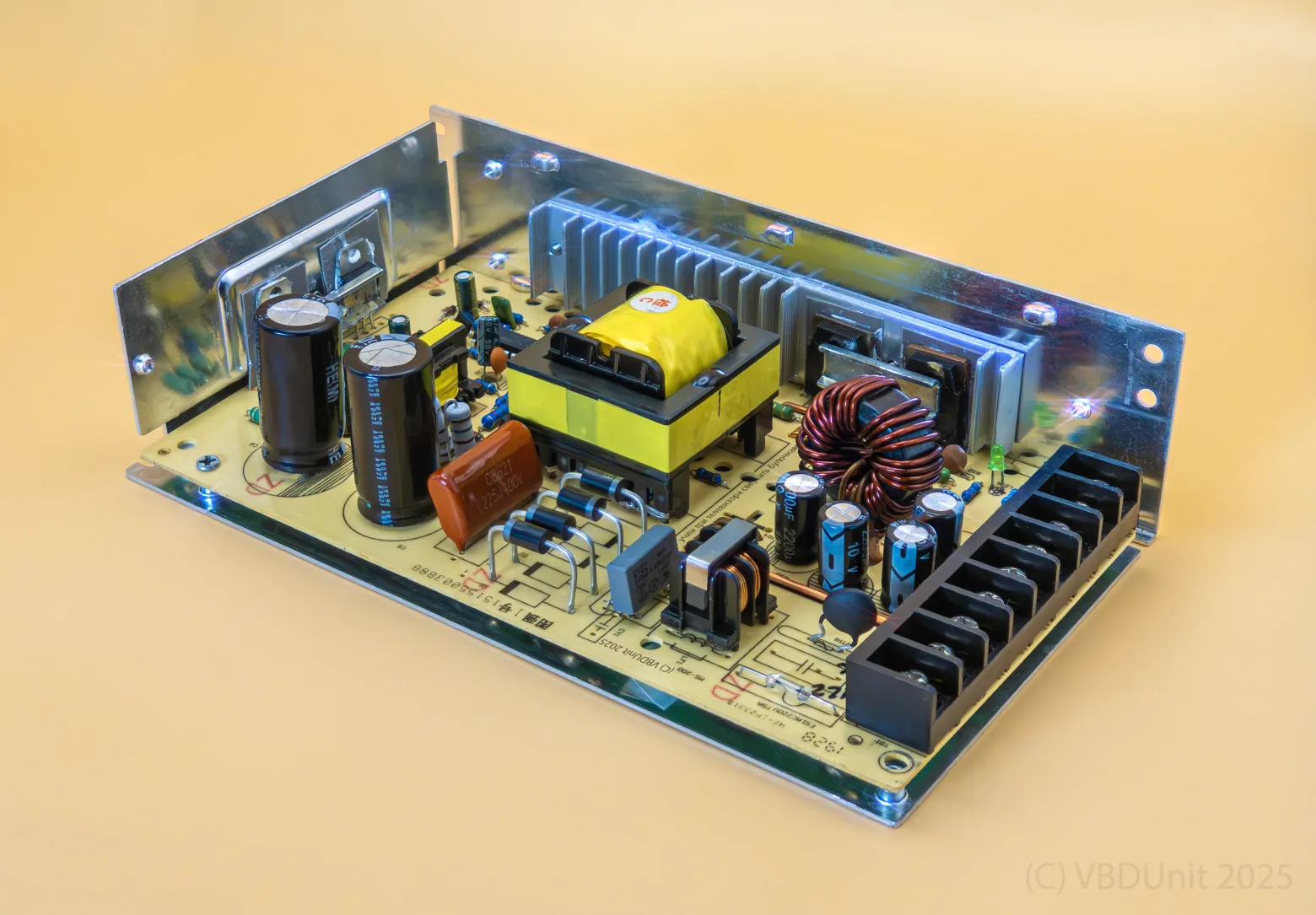
The system needed approximately 450W of peak power at 5V — roughly 90 amperes. Rather than using a single massive power supply (which would be physically huge and create a single point of failure), the author distributed three 200W power supplies, one per television. Each supply feeds its respective monitor's LED strips through 2.5mm-squared multicore cables.
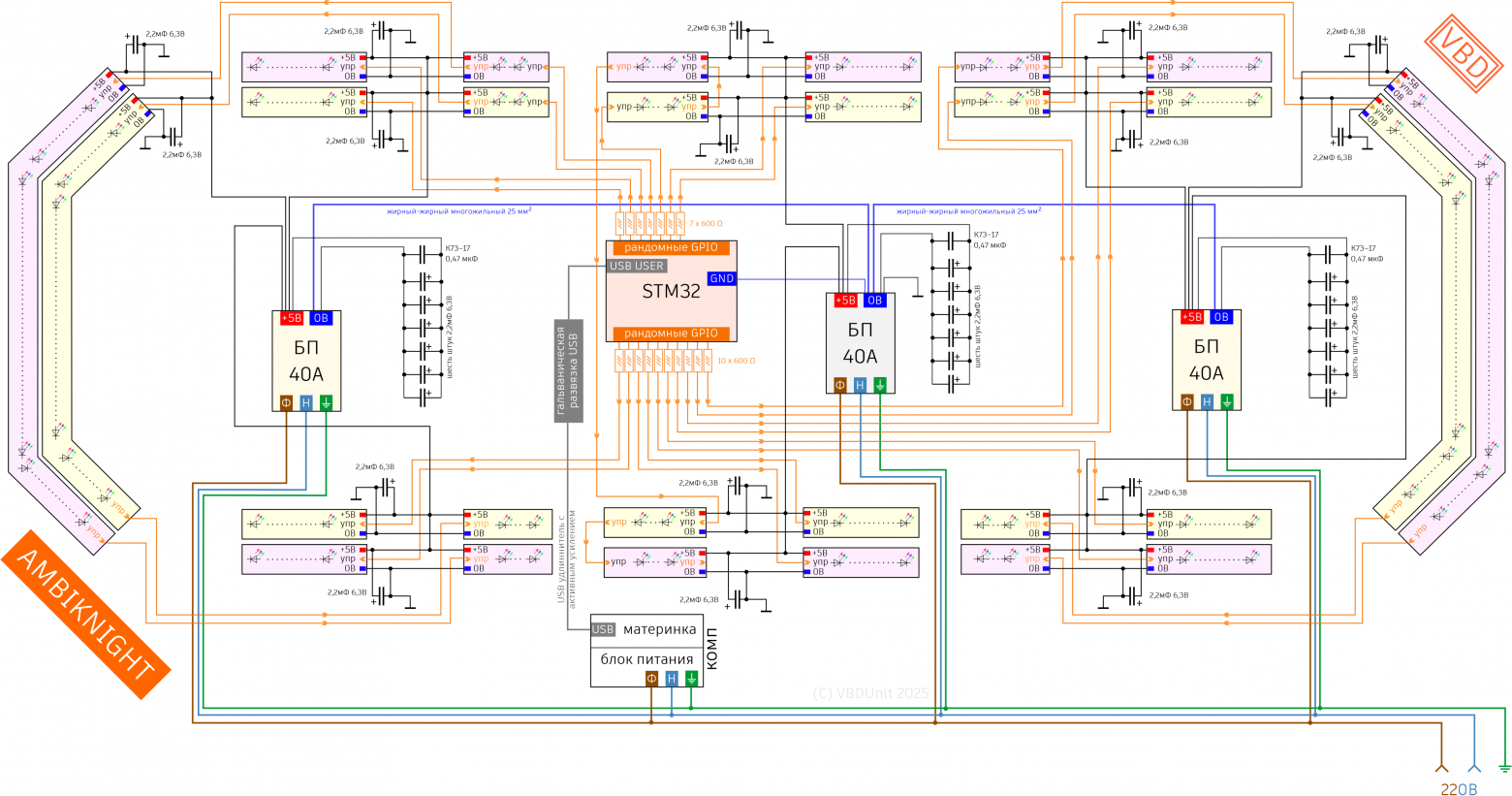
The critical mistake came early: initially connecting the power supplies' common rails with thin wire. When current demand shifted rapidly between zones (as different parts of the video wall lit up), the thin interconnect couldn't handle the equalization current. Voltage fluctuations caused regulation failures in individual supplies, which cascaded into destroying the first controller.
The fix was dramatic: upgrading the common connection to 25mm-squared welding-grade copper cable — the kind used for arc welding. This massive conductor ensured adequate current-sharing between all three power supplies regardless of load distribution.
The Capacitor Invasion

The initial controller failures led to a comprehensive energy buffering strategy. Each of the eight LED segments received two 2200 microfarad / 6.3V electrolytic capacitors — sixteen in total — providing local energy storage right at the point of consumption. These absorb the current spikes that occur during sudden brightness changes, preventing the voltage from sagging enough to reset the controller.
Upgrading the Power Supplies
But local capacitors alone weren't enough. The author designed custom "snail" modules — small assemblies containing six electrolytic capacitors plus 0.47 microfarad film capacitors — and installed them inside each power supply. The film capacitors handle the highest-frequency current transients that electrolytics are too slow to catch. These modules act as an energy buffer between the power supply's regulation loop and the sudden demands of hundreds of LEDs switching simultaneously.
Controller and Management System
The system needed to control 17 independent addressable LED strips simultaneously, all using the WS2812b protocol. This protocol is notoriously timing-sensitive: each bit requires precise pulses measured in hundreds of nanoseconds. Controlling a single strip is trivial; controlling 17 in parallel while maintaining timing integrity is a fundamentally different problem.
The Thorny Path to Parallelism
Attempt 1: Arduino Mega 2560
The first platform tested was the Arduino Mega 2560. It failed on two counts: insufficient RAM to hold the frame buffer for 2,315 pixels (each needing 3 bytes for RGB, totaling nearly 7 KB — feasible in isolation but unworkable alongside the protocol overhead), and insufficient processing speed to maintain timing across 17 parallel outputs. The Arduino's 16 MHz clock simply couldn't toggle GPIO pins fast enough while managing the protocol state machine for multiple strips.
Attempt 2: Raspberry Pi 4B
The Raspberry Pi 4B had more than enough raw processing power, but Linux is not a real-time operating system. The kernel scheduler, interrupt handlers, and background services all compete for CPU time. The WS2812b protocol requires uninterrupted 400-nanosecond pulse accuracy. On the Pi, random scheduling jitter corrupted the timing, producing flickering and color artifacts. No amount of process priority tuning or CPU core isolation could guarantee the deterministic timing needed.
Attempt 3: STM32 Discovery F7
The STM32F7 Discovery board was the winning platform. With a 216 MHz ARM Cortex-M7 core, direct GPIO access, and no operating system to interfere, it provided both the speed and determinism needed. The author could directly control 20 GPIO pins simultaneously with instruction-level timing precision.
Writing the WS2812b Protocol by Hand
Standard WS2812b libraries operate on one strip at a time. For parallel operation across 17 strips, the author had to implement the protocol from scratch. The key insight was reformulating the timing: instead of the standard asymmetric pulses (800ns high + 450ns low for a "1" bit, 400ns high + 850ns low for a "0" bit), the author broke each bit period into three equal 400-nanosecond phases:
- Phase 1: All outputs HIGH (start of bit)
- Phase 2: Output the actual data bit (HIGH for "1", LOW for "0")
- Phase 3: All outputs LOW (end of bit)
This symmetric scheme still falls within the WS2812b's timing tolerance window while being far simpler to implement in parallel — all 17 strips receive their respective bits simultaneously in the same three-phase cycle.
The implementation uses direct memory access to GPIO registers with interrupt blocking during the critical timing window. A code generator produces 72 pre-calculated variable assignments and corresponding NOP instruction sequences that precisely time each GPIO state transition. Every instruction counts: at 216 MHz, each clock cycle is approximately 4.6 nanoseconds, so achieving 400ns windows requires carefully counted chains of roughly 86 NOPs or equivalent instructions.
In the Coaxial Web

Signals traveling over 1-meter coaxial cables to the LED strips needed protection from electromagnetic interference and from an unexpected failure mode. Each strip connection includes a 600-ohm series resistor. These resistors serve a dual purpose: they limit the signal current to safe levels, and more importantly, they prevent a dangerous backfeed scenario.
When the LED power supplies are turned off while the controller remains powered (via USB), the LED strips attempt to draw current through the data signal lines. Without the series resistors, this parasitic current path destroyed the first controller. The 600-ohm resistors limit fault current to safe levels under all power sequencing scenarios.
The coaxial shielding maintains signal integrity over the cable runs, preventing the fast digital edges from radiating interference to neighboring cables or picking up noise from the power supply switching.
Debugging and Setup
The final piece of the puzzle was galvanic USB isolation between the computer and the STM32 controller. This was added after the author experienced mysterious, periodic computer shutdowns that seemed unrelated to the LED project. It turned out that potential differences between the computer's ground and the LED power supply ground were creating current loops through the USB cable. A galvanic isolation adapter broke this loop completely, eliminating the shutdowns and providing an added layer of protection for both the computer and the controller.
Conclusion
The finished system drives 2,315 addressable LEDs across 17 strips from a single STM32 controller, powered by three independent 200W supplies tied together with welding cable. Every component in the chain — from the film capacitors inside the power supplies to the 600-ohm series resistors on each signal line to the galvanic USB isolator — was added because something broke or misbehaved without it. The project is a textbook example of how seemingly simple LED projects escalate into serious power electronics and signal integrity challenges when you push the scale far enough.


