Building a Processor from Scratch
A hands-on guide to building an 8-bit RISC processor in a logic circuit simulator, starting from basic binary logic gates and working up through adders, multiplexers, memory, and the BitBitJump one-instruction architecture.
Building a Processor from Scratch
For as long as I can remember, I've always dreamed of building a processor. Finally, yesterday I built one. Nothing fancy: 8-bit, RISC, current operating frequency of 4 kHz, but it works. For now it runs in a logic circuit simulation program, but we all know: "today in simulation, tomorrow in reality!"
Below you'll find several animations, a brief introduction to binary logic for absolute beginners, a short explanation of the main logic chips in a processor, and the circuit diagram itself.
Binary Logic
The binary number system (for those who don't know) is a number system in which there are no digits greater than one. This definition confuses many people until they remember that in the decimal number system there are no digits greater than nine.
The binary system is used in computers because numbers in it are easy to encode with voltage: there's voltage — that means one; no voltage — that means zero. Furthermore, "zero" and "one" can easily be understood as "false" and "true". Moreover, most devices operating in the binary number system typically treat numbers as arrays of "truths" and "falsehoods", meaning they operate on numbers as logical values. For absolute beginners and those not in the know, I'll explain and show how the simplest elements of binary logic work.
The "Buffer" Element
Imagine you're sitting in your room and your friend is in the kitchen. You shout to them: "Hey, tell me, is the hallway light on?" Your friend replies: "Yes, it's on!" or "No, it's off." Your friend is a buffer between the signal source (the hallway light bulb) and the receiver (you). Moreover, your friend isn't just some ordinary buffer — they're a controlled buffer. They would be an ordinary buffer if they constantly shouted: "The light is on" or "The light is off."
The "NOT" Element
Now imagine that your friend is a joker who always tells lies. If the hallway light is on, they'll tell you "No, the hallway is completely dark," and if it's off, they'll say "Yes, the hallway light is on." If you actually have such a friend, then they are the embodiment of the NOT element.
The "OR" Element
To explain the OR element, one light bulb and one friend unfortunately aren't enough. You need two light bulbs. So, you have two light bulbs in the hallway — a floor lamp and a chandelier, for example. You shout: "Hey, is at least one light bulb in the hallway on?" and your friend answers "Yes" or "No." Obviously, for the answer to be "No," all light bulbs must be turned off.
The "AND" Element
Same apartment, you, friend in the kitchen, floor lamp and chandelier in the hallway. To your question "Are both light bulbs in the hallway on?" you get the answer "Yes" or "No." Congratulations, now your friend is an AND element.
The "Exclusive OR" Element — XOR
Let's repeat the OR element experiment, but rephrase the question to your friend: "Hey, is only one light bulb on in the hallway?" An honest friend will answer "Yes" only if indeed just one light bulb is on in the hallway.
Adders
Quarter Adder
The XOR element is called a quarter adder. Why? Let's figure it out.
Let's make an addition table for two numbers in the binary number system:
- 0 + 0 = 0
- 0 + 1 = 1
- 1 + 0 = 1
- 1 + 1 = 10
Now let's write out the truth table for the XOR element. We'll denote a lit light bulb as 1, an unlit one as 0, and your friend's "Yes"/"No" answers as 1 and 0 respectively.
- 0 XOR 0 = 0
- 0 XOR 1 = 1
- 1 XOR 0 = 1
- 1 XOR 1 = 0
Looks very similar, doesn't it? The addition table and the XOR truth table match completely, except for one single case. And that case is called "overflow."
Half Adder
During overflow, the result of addition no longer fits in the same number of digits as the operands. The operands are two single-digit numbers (one significant digit, see?), but the sum is already a two-digit number (two significant digits). You can't transmit two digits with one light bulb ("On"/"Off"). You need two light bulbs. Need it — done!
Besides XOR, we also need the AND element for our adder.
- 0 XOR 0 = 0; 0 AND 0 = 0
- 0 XOR 1 = 1; 0 AND 1 = 0
- 1 XOR 0 = 1; 1 AND 0 = 0
- 1 XOR 1 = 0; 1 AND 1 = 1
Ta-da!
- 0 + 0 = 00
- 0 + 1 = 01
- 1 + 0 = 01
- 1 + 1 = 10
Our half adder works. It can be considered the simplest specialized processor that adds two numbers. A half adder is called a half adder because it cannot account for carry (the result of another adder's work), meaning you cannot add three single-digit binary numbers. Because of this, you can't build a multi-bit adder from several single-bit half adders.
I won't go into the details of full adders and multi-bit adders; I just hope you've grasped the basic idea.
More Complex Elements
Multiplexer
Let me invite you to use your imagination again. Picture this: you live in a single-unit private house, and next to the door stands your mailbox. Going out for a walk, you notice a strange mailman standing near that very mailbox. Here's what he does: he pulls a bunch of letters from his bag, reads the number on the mailbox, and depending on the number on the box, drops in one letter or another. The mailman is working as a multiplexer. He determines in a specific way (the number on the envelope) which signal (letter) to send through the signal line (mailbox).
Multiplexers usually consist only of combinations of AND, OR, and NOT elements. A single-bit multiplexer has one input called "address select," two inputs collectively called "input signal," and one output simply called "output signal." When 0 is applied to "address select," the "output signal" becomes the same as the first "input signal." Correspondingly, when 1 is applied to "select," the "output signal" equals the second "input signal."
Demultiplexer
This gadget works in exactly the opposite way. You feed the address to "address select," feed the data to "data input," and at the output numbered "address" you get the data from the input.
Counter
To understand how a counter works, you'll need your friend again. Call them from the kitchen (I hope they weren't too bored there, and most importantly, didn't eat all your food), and ask them to do the following: let them remember the number 0. Each time you touch them, they must add one to the number they remember, say the result, and remember it. When the result equals (let's say) 3, they must shout "Abracadabra!" and answer on the next touch that they now remember the number 0. A bit complicated? Watch:
You touch your friend. Friend says "One."
You touch your friend. Friend says "Two."
You touch your friend. Friend says "Three." Friend shouts "Abracadabra!" Critical hit! You are temporarily paralyzed and cannot move.
You touch your friend. Friend says "Zero."
And so on. Very simple, right? You've surely realized that your friend is now a counter. Touching your friend can be considered the "clock signal" or, simply put, the count-continue signal. The "Abracadabra" shout indicates that the stored value in the counter is at maximum, and that on the next clock signal the counter will be reset to zero. There are two differences between a binary counter and your friend. First: a real binary counter outputs its stored value in binary form. Second: it always does only what you tell it and never stoops to silly jokes that could disrupt the entire processor system.
Memory
Flip-Flop (Trigger)
Let's continue tormenting your poor (possibly imaginary) friend. Now let them remember the number zero. When you touch their left hand, they must remember zero, and when you touch their right hand — the number one. When asked "What number do you remember?" your friend must always answer with the number they memorized — zero or one.
The simplest memory cell is the RS flip-flop ("trigger" means "switch"). An RS flip-flop can store one bit of data ("zero"/"one") and has two inputs. The Set input (just like your friend's left hand) writes "one" into the flip-flop, and the Reset input (correspondingly, the right hand) writes "zero."
Register
A register is a bit more complex. Your friend becomes a register when you ask them to remember something, and then you say "Hey, remind me what I told you to remember?" and your friend answers correctly.
A register can usually store a bit more than one bit. It always has a data input, a data output, and a write-enable input. From the data output, you can read what's stored in the register at any time. You can apply whatever data you want to write to the data input. You can keep feeding data as long as you like. Nothing will actually be written to the register until you apply a one, a "logical one," to the write-enable input.
Shift Register
Have you ever stood in line? Surely you have. Then you know what it's like to be data in a shift register. People arrive and join the end of the line. The first person in line enters the big boss's office. Whoever was second becomes first, and whoever was third is now second, and so on. A queue is a clever shift register from which "data" (that is, people) can run off on errands after warning their queue neighbors. In a real shift register, of course, "data" cannot escape the queue.
So, a shift register has a data input (through which data enters the "queue") and a data output (from which you can read the very first entry in the "queue"). The shift register also has a "shift register" input. As soon as a "logical one" arrives at this input, the entire queue shifts.
There's one important difference between a queue and a shift register. If a shift register is designed for four entries (for example, four bytes), then the first entry in the queue will only reach the register's output after four signals to the "shift register" input.
RAM (Random Access Memory)
If you combine lots and lots of flip-flops into registers, and lots and lots of registers into one chip, you get a RAM chip. A memory chip usually has an address input, a bidirectional data port (meaning you can write to and read from this port), and a write-enable input. You apply some number to the address input, and that number selects a specific memory cell. After that, at the data input/output you can read what's stored in that particular cell.
Now, we simultaneously apply to the data input/output whatever we want to write to that cell, and apply a "logical one" to the write-enable input. The result is slightly predictable, isn't it?
The Processor
BitBitJump
Processors are sometimes divided into CISC — those that can execute many different instructions, and RISC — those that can execute few instructions but execute them well. One fine evening I thought: wouldn't it be cool if you could build a full-fledged processor that can execute just one instruction? I soon learned that there's an entire class of one-instruction processors — OISC, most commonly using the Subleq instruction (subtract, and if less than or equal to zero, jump) or Subeq (subtract, and if equal to zero, jump). While studying various OISC processor designs, I found on the internet the website of Oleg Mazonka, who developed the simplest one-instruction language called BitBitJump. The sole instruction of this language is called exactly that — BitBitJump (copy a bit and jump to address). This undoubtedly esoteric language is Turing-complete — meaning any computer algorithm can be implemented in it.
A detailed description of BitBitJump and an assembler for this language can be found on the developer's website. To describe the processor's algorithm, you need to know the following:
- When the processor powers on, registers PC, A, and B contain 0
- Read the memory cell at address PC and save the value to register A
- Increment PC
- Read the memory cell at address PC and save the value to register B
- Increment PC
- Write to the cell at the address stored in register B the contents of the bit at address A
- Read the memory cell at address PC and save the value to register B
- Write the contents of register B to register PC
- Go to step 2
- PROFIT!!!
Unfortunately, the algorithm is infinite, so PROFIT will never be achieved.
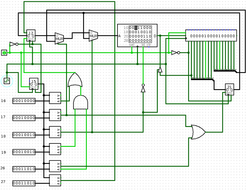
The Circuit Diagram
The circuit was built spontaneously, so fear, horror, and chaos reign supreme within it. Nevertheless, it works, and works decently. To turn on the processor, you need to:
- Enter the program into RAM
- Press the power switch
- Set the counter to position 4 (this could be done in hardware too, but the circuit would become even more unwieldy)
- Turn on the clock generator
As you can see, the design uses one register, one shift register, one RAM chip, two binary counters, one demultiplexer (represented by comparators), two multiplexers, and a bit of pure logic.
You can download the circuit in .circ format for the Logisim program and play around with it.
What's Next?
First, you can increase the processor's bit width — replacing 8-bit elements with 16-bit ones.
Second, you can move the RAM outside the processor and add a simple circuit that pauses the processor, modifies the RAM, and turns the processor back on. Such a circuit would serve as a simple I/O controller. Then you could build a calculator, controller, or some other amusing useless gadget based on this processor.
Third, you can implement this entire circuit in hardware. Which is exactly what I plan to do. As soon as I do — I'll definitely share and show it.
Thank you all for your attention!
P.S. Links (for those too lazy to read):
- URISC processors — ru.wikipedia.org/wiki/Urisc
- BitBitJump language website — mazonka.com/bbj/index.html
- Logic circuit simulation program Logisim — ozark.hendrix.edu/~burch/logisim/
- Homemade URISC (ORISC) processor for Logisim — narod.ru/disk/31367690001/oo.circ.html


