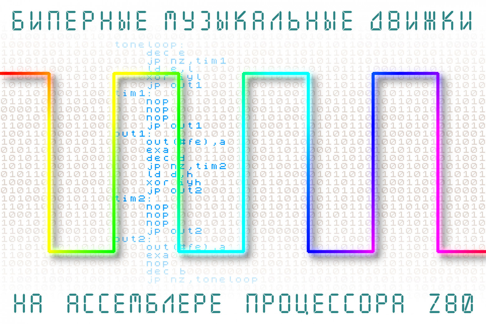
Beeper Music Engines in Z80 Assembly
An in-depth exploration of one-bit music synthesis on the ZX Spectrum, from basic square wave generation through two-channel polyphony, covering clock cycle calculations, hardware timing quirks, and a complete functional music engine in Z80 assembly.
Computers with one-bit audio output — like the ZX Spectrum — had no dedicated sound hardware. All they had was a single bit that could be flipped between 0 and 1, connected to a tiny speaker. Yet programmers managed to create surprisingly complex music using nothing but precisely timed CPU instructions. Let's trace the development from basic concepts through a complete functional music engine written in Z80 assembly.
A Brief History of Beeper Music
The Early Computing Era (1949-1950s)
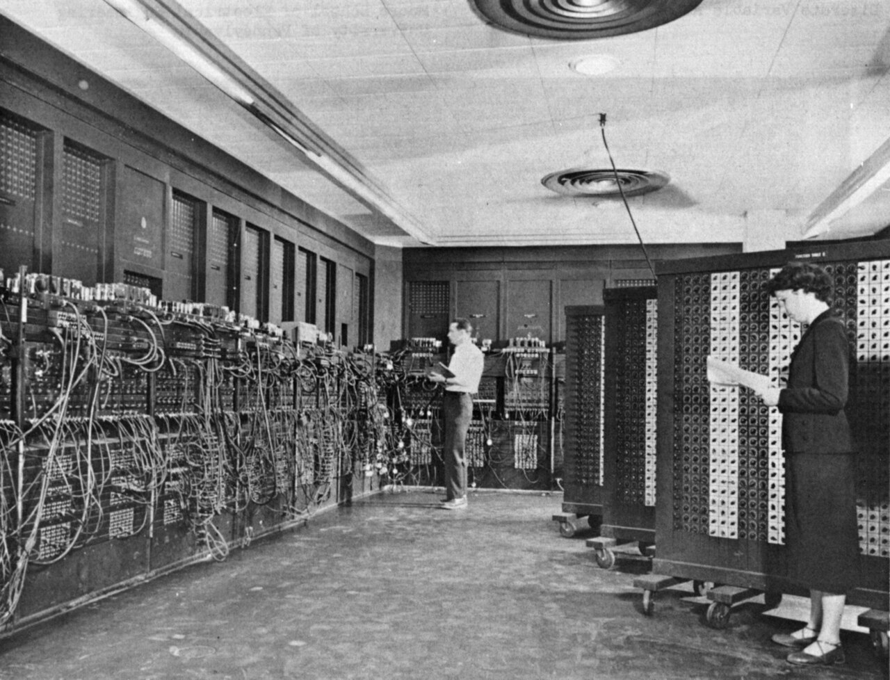
The first computer music dates back to 1949, when the BINAC produced a melody. The TX-0 and PDP-1 computers later generated tones through software timing. Alan Turing documented the theoretical foundations in 1950. Sound was captured via radio interference, control lamps, or external speakers connected to output ports.
The Home Computer Era (1975-1985)
Early home systems like the Altair 8800 had no audio output at all. The Sol-20 introduced the integrated keyboard computer format. The Music System (Software Music Synthesis System) achieved three-voice synthesis on Intel 8080 machines. The Apple II and ZX Spectrum added built-in speakers but still had no hardware synthesis — game developers had to create complex audio using just a single-bit output.
Technical Foundation: Basic Principles
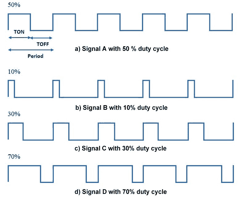
To generate sound on a one-bit output, you toggle between 0 and 1 states at precise intervals. Shorter intervals produce higher frequencies; longer intervals produce lower frequencies. A square wave has equal on and off durations.
The basic pseudocode is:
loop:
    set output to 1
    wait N/2 time
    set output to 0
    wait N/2 time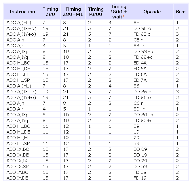
Clock Cycle Calculations
The Z80 processor in the ZX Spectrum runs at 3.5 MHz. Each instruction consumes a specific number of clock cycles ("tacts"). For example:
NOP— 4 tactsOUT (#fe),a— 11 tactsXOR #10— 7 tacts
Instructions per second = 3,500,000 / tacts per instruction. Timing must be manually planned and verified for every instruction in the loop.
ZX Spectrum Hardware Specifics
Port #FE Architecture
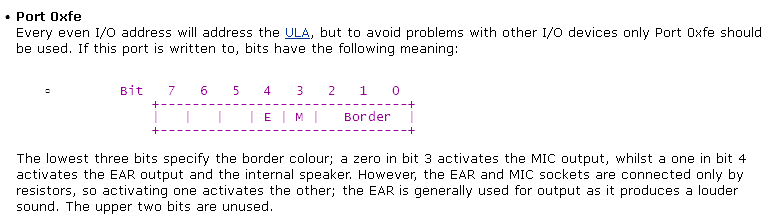
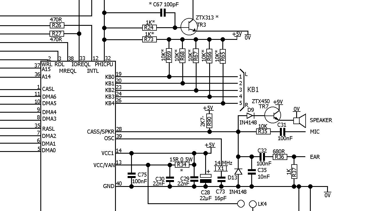
The ZX Spectrum's I/O port #FE controls multiple functions:
- Bit D4: beeper output
- Bit D3: cassette tape output
- Bits D2-D0: border color (screen edges)
Both the beeper and tape bits share the physical output through the ULA chip. Different voltage levels create a quasi-two-bit DAC effect, though this is mostly ignored in practice.
Memory Timing Issues
Three critical timing issues affect sound quality:
- Memory contention: RAM access shares bandwidth with the video system. The lower 16 KB (ROM) has no slowdown, but the upper 32 KB experiences variable slowdown from video rendering. Code must run from address #8000 or higher for clean sound.
- Port I/O contention: Output instruction timing varies based on CPU timing within 8-tact cycles. You must maintain 8-tact alignment for consistent output timing.
- Interrupt management: System interrupts introduce 50 Hz noise. You must disable interrupts (
DI) during sound synthesis.
Implementation: Simple Single Tone
The simplest approach toggles the beeper bit in a tight loop:
    ld a,0              ; initialize output bit
loop:
    out (#fe),a         ; 11 tacts
    nop                 ; 4 tacts (multiply for lower frequencies)
    xor #10             ; 7 tacts (toggle bit D4)
    jp loop             ; 10 tacts
Cycle duration: 11 + 4 + 7 + 10 = 32 tacts. Frequency: 3,500,000 / 32 / 2 = approximately 54,687 Hz (ultrasonic — too high to hear!).
Programmable Frequency
To produce audible tones, we add a delay loop controlled by a register:
    ld a,0
loop:
    out (#fe),a         ; 11
    ld b,N              ; 7
delay:
    dec b               ; 4
    nop                 ; 4
    jp nz,delay         ; 10
    xor #10             ; 7
    jp loop             ; 10
The formula for calculating the delay counter N for a desired frequency F:
N = ((3,500,000 / F / 2) - 35) / 18For 440 Hz (concert A): N = approximately 219, which fits in an 8-bit register.
Two-Channel Polyphony
The "Music Box" approach (dating from 1985) achieves two simultaneous voices by rapidly alternating between two tone generators at over 15 kHz. Key techniques include:
- Counter/divider method instead of delay loops
- Register swapping using the
EXAinstruction for parallel operation - Equal-duration code branches to prevent frequency crosstalk
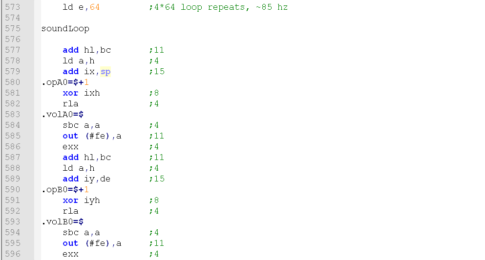
The implementation stores two frequency dividers in registers H and L, maintaining counters for each channel in D and E. Output alternates between channels every iteration. Total cycle: 110 tacts. Sampling rate: 3,500,000 / 110 = approximately 31,818 Hz.
Frequency calculation for the two-channel system:
Divider = (31,818 / Desired_Frequency) / 2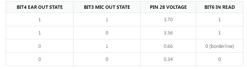
Noise Effects
Simple white noise can be generated by outputting pseudorandom data from ROM (the 16 KB of fixed ROM content serves as a noise source):
    ld bc,1000          ; duration counter
loop:
    ld a,(bc)           ; read ROM byte
    and #10             ; isolate beeper bit
    out (#fe),a         ; output
    dec bc              ; decrement counter
    ld a,b
    or c                ; check if BC = 0
    jp nz,loop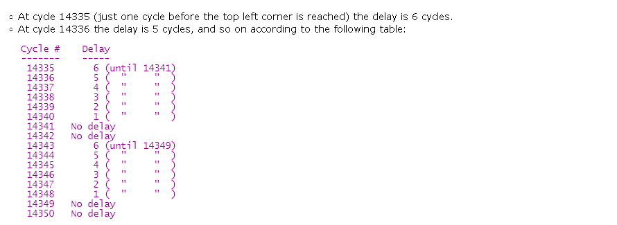
Complete Music Engine
The full engine has three components:
- Sound synthesis — the two-tone generator loop
- Data parser — reads musical notation from memory
- Note sequencer — manages timing and effects
The music data format uses special byte values:
- Byte 255: loop marker (next 2 bytes specify the target address)
- Byte 254: trigger noise/drum effect
- Byte pairs: frequency dividers for each channel (0 = pause/silence)
The parser supports tempo control in 1/16th note increments, two melodic channels plus percussion, and automatic cycling with loop support.
Helper Script for Note Generation
A Python utility generates assembler constants for musical notes:
sample_rate = (3500000.0 / 120.0)
note_frequency = [2093.0, 2217.4, 2349.2, ...]
note_names = ["C_", "Ch", "D_", ...]

for notes in range(note_min, note_max + 1):
    note = int(notes % 12)
    octave = int(notes / 12)
    div = float(32 >> octave)

    step = sample_rate * 2.0 / (note_frequency[note] / div)
    if step >= 253:
        step = 253

    print('%s%i\t\tequ %i' % (note_names[note], octave, int(step)))
This generates readable constants like:
A_2     equ 132
C_4     equ 55
E_5     equ 22
Music Data Example
music_data:
    db A_2,C_4      ; simultaneous A2 and C4
    db R__,R__      ; silence
    db A_2,R__      ; A2 alone
    db R__,R__
    db DRUM         ; trigger noise effect
    ; [pattern repeats with variations]
    db EOF          ; end marker
Key Technical Insights
- Precision requirement: Timing accuracy is critical — one miscount produces audible distortion
- Register constraints: Limited 8-bit registers force 8-bit dividers, reducing frequency resolution
- Timing trade-offs: Higher channel count requires faster CPU cycling, introducing an audible 15+ kHz carrier tone
- Hardware variations: Different Spectrum models (48K vs 128K vs +3) have different contention patterns
- Practical limitations: 8-bit dividers yield approximately 36 frequency steps per octave (compared to 12 in equal temperament), so slight detuning was common in retro games

Creating even "simple" two-channel music on 8-bit hardware demanded intimate knowledge of processor architecture, memory timing, and electrical hardware. Every instruction had to be manually counted for clock cycles. It represents an extreme optimization exercise — one that pushed programmers to extract remarkable results from impossibly limited hardware.
FAQ
What is this article about in one sentence?
This article explains the core idea in practical terms and focuses on what you can apply in real work.
Who is this article for?
It is written for engineers, technical leaders, and curious readers who want a clear, implementation-focused explanation.
What should I read next?
Use the related articles below to continue with closely connected topics and concrete examples.