August 2009: The Sayano-Shushenskaya Dam Disaster
A detailed technical examination of the catastrophic failure at the Sayano-Shushenskaya hydroelectric power station on August 17, 2009, which killed 76 people and destroyed the turbine hall — while the dam itself remained intact.
Important clarification: This material is neither entertainment nor a strict technical investigation. It represents minimal technical education. If readers gain proper understanding and cease spreading misinformation, the goal succeeds. The text divides into two parts within one article.
Part One: Water and Concrete
The Triggering Event
Irkutsk Oblast, Bratsk Hydroelectric Station on the Angara River. Night of August 16-17, 2009.
At 20:20 Moscow Time (01:20 local time), fire services received a report of a fire in the communications equipment room at "Irkutskenergosviaz," leased from Bratsk Dam.
Investigation revealed no actual fire — merely a short circuit damaging electronic equipment. The damaged electronics had no operational role, seemingly posing no threat to the station.
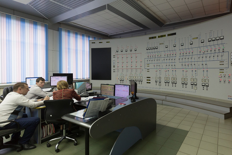
However, dispatcher communications systems failed: turbine shops lost contact with hydro divisions; crane operators couldn't report conditions; the duty engineer received no generator data regarding frequency, power, current, or voltage. The station went blind.
By the twenty-first century, mobile phones enabled operations to continue through the night in near-normal conditions. Repairs and administrative consequences loomed, but seemingly manageable.
Decreased energy output proved unthinkable. The unified Russian power system required compensating elsewhere. At 20:31 Moscow Time, Sayano-Shushenskaya's aggregate #2 activated.
Eight hours later, catastrophe struck — claiming seventy-six lives and destroying equipment worth astronomical sums, damaging the reputation of hydroelectric engineers nationwide.
What Occurred
Khakassia Republic, Sayano-Shushenskaya Dam on the Yenisei River. Morning of August 17, 2009.
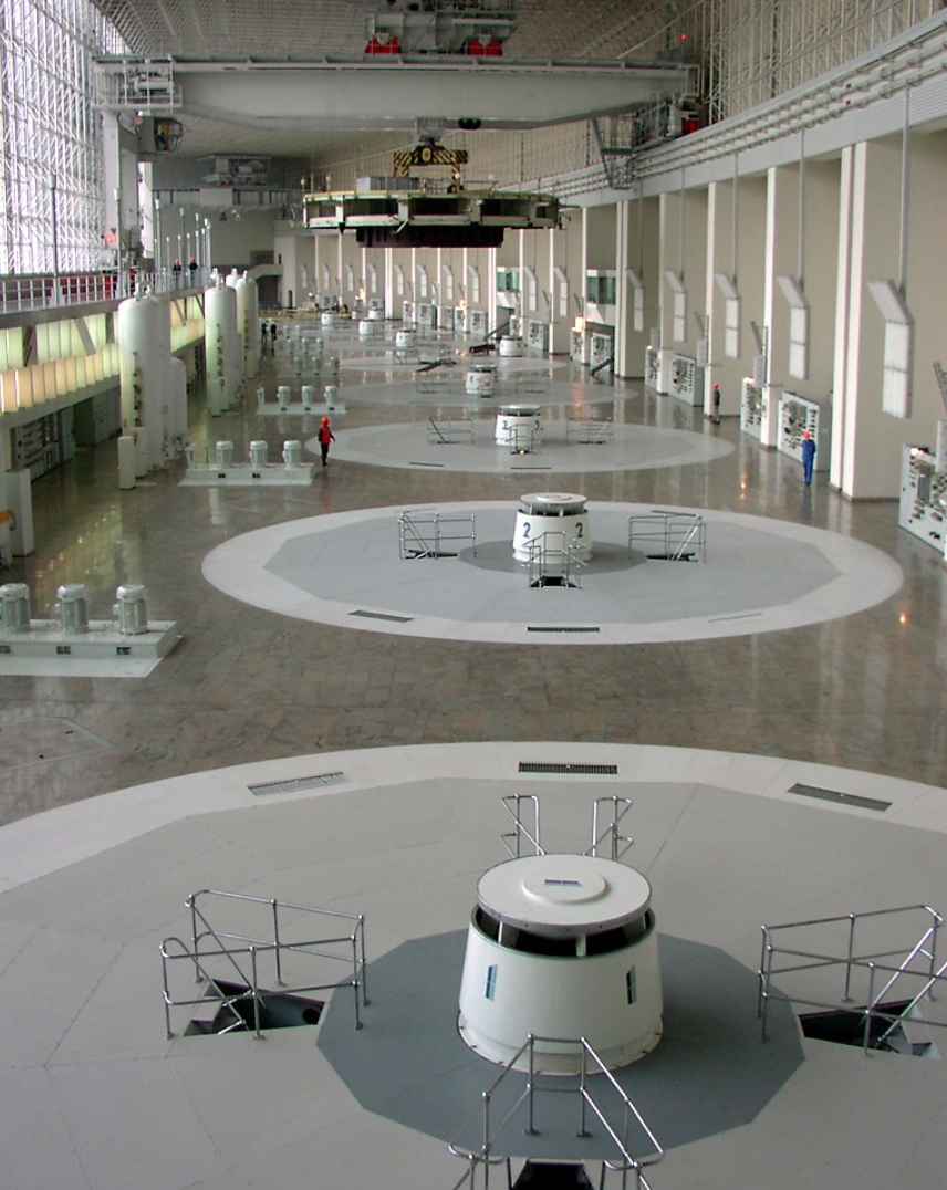
Everything happened on an ordinary Monday morning. By 8 a.m., station personnel dispersed to supervisory offices for weekly planning, shift changes, and safety briefings. The machine hall stood nearly empty — night shift crews handing over to day shift, with only janitorial and security personnel unaware the station operated in forbidden conditions.
Did they sense stronger-than-usual floor vibrations? Probably not — vibration never ceases in machine halls, and nine of ten aggregates running simultaneously was exceptionally rare.
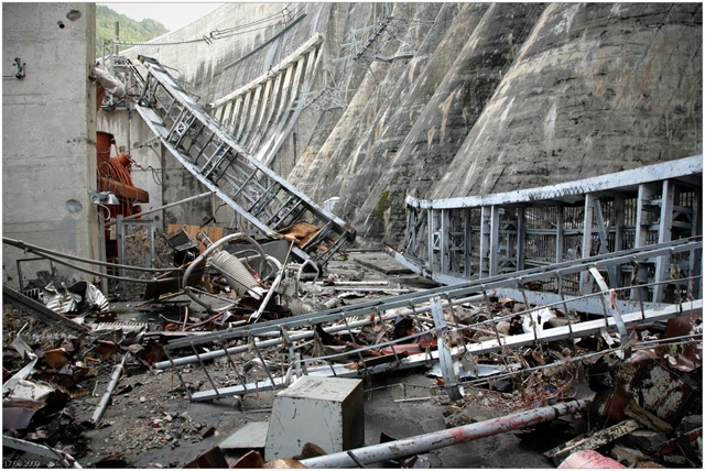
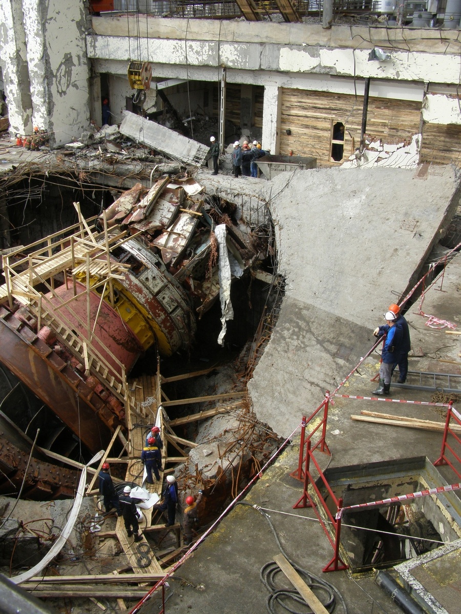
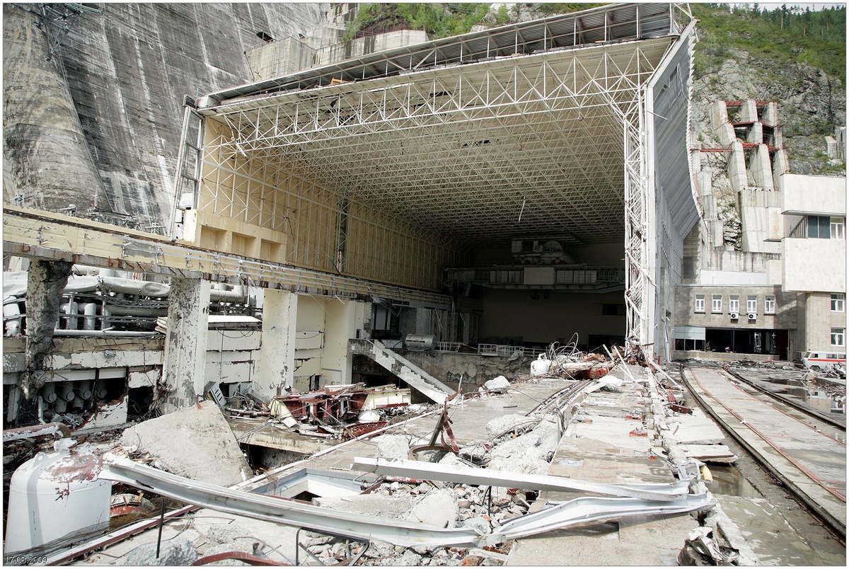
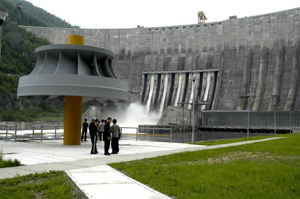
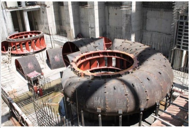
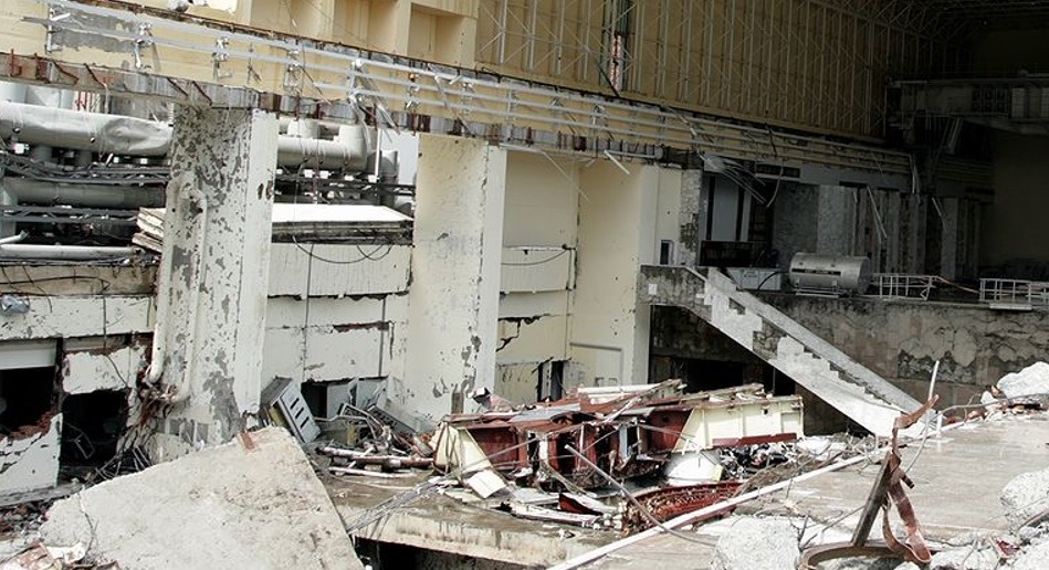
At 04:13 Moscow Time (08:13 local), a powerful explosion-like sound erupted at aggregate #2's location. Massive water pressure burst the damaged aggregate's cover, launching the rotating turbine twelve meters upward. Falling and overturning, it functioned like an enormous drill bit, shattering the concrete base. A fountain of such force swept through the machine hall's gleaming glass-and-marble structure like a tsunami. From that moment, the station was doomed.
The Dam Versus The Powerhouse
Here lies tremendous temptation to sensationalize details, assign blame, publish photographs of devastation. Resist it. Instead, let's rationally examine hydroelectricity fundamentals.
Civilians conflate "dam" and "hydroelectric station." The distinction proves crucial.
A dam exists solely to hold water, creating reservoirs. Dams predate electricity by millennia. They stored water against drought, prevented flooding, drained riverbeds for construction, and redirected water through channels or pipes.
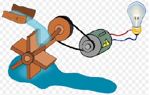
Electrical stations fundamentally require something rotating an electrical generator shaft. Rotation sources vary: steam, diesel engines, windmills, or muscle power. Hydroelectric stations specifically use dams to maximize water falls onto turbine blades, increasing shaft rotation speed. Technically, dams aren't mandatory — natural waterfalls work (Niagara's dam includes hydroelectric capacity). Tidal and geyser energy attempts exist but remain exotic.
When initial disaster reports reached downstream Yenisei cities (Sayanogorsk, Minusinsk, Abakan), panic erupted: vehicles fled to highlands; gasoline sold instantly; frightened refugees watched their homes, awaiting apocalyptic flooding. Most assumed Sayano-Shushenskaya resembled destroyed wartime dams.
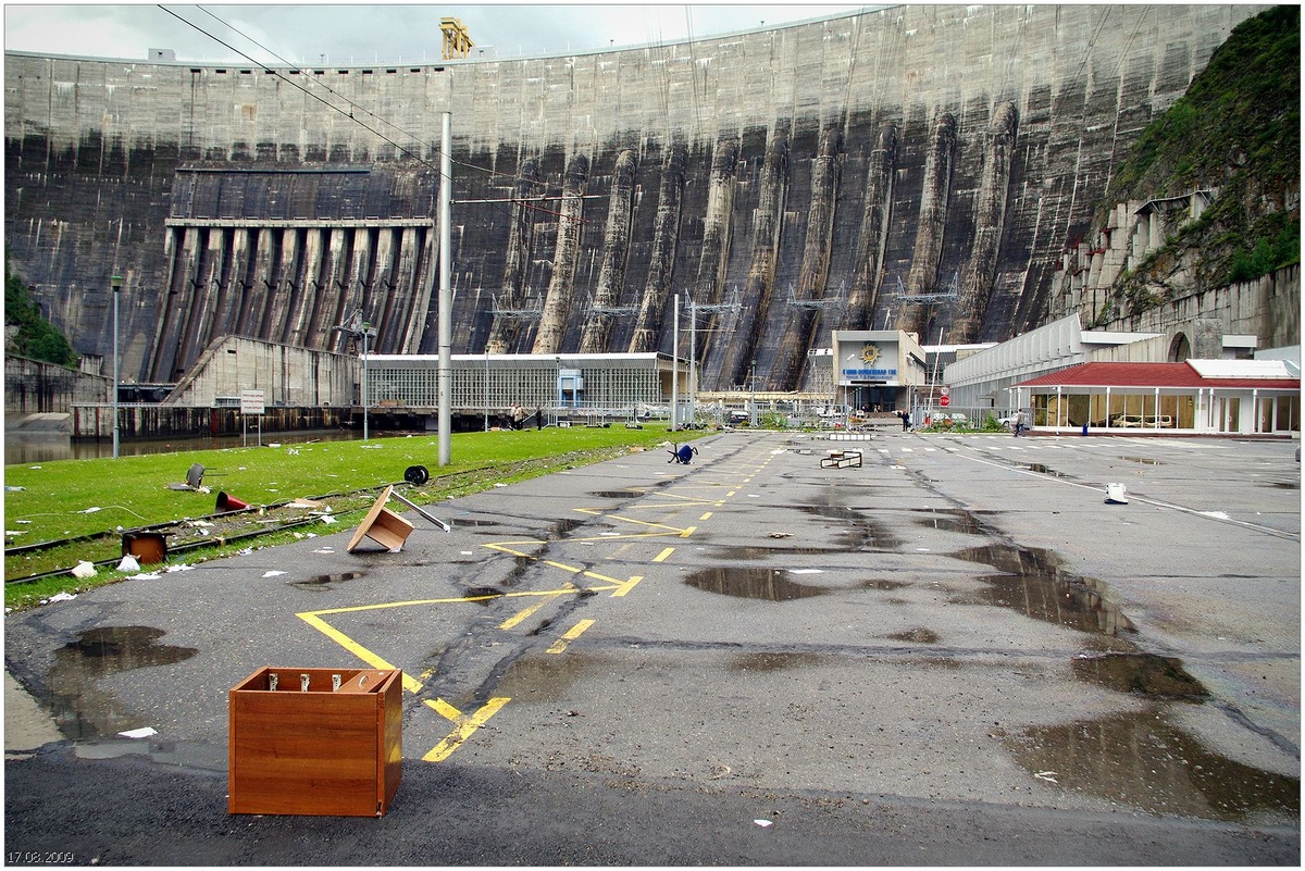
Actually, the catastrophe completely destroyed electrical equipment — turbines, generators, transformers, switchgear. The dam structure remained intact. Concrete water conduits noticed nothing. Interior galleries stayed dry.
Historical Fissures
Khakassia Republic, Sayano-Shushenskaya, 1991-1995
Nobody should condemn frightened refugees — Hollywood catastrophe films condition expectations toward worst scenarios.
Consider this analogy: the dam is your hand; the power station is a wristwatch. Destroying the watch while the hand remains healthy is entirely possible — precisely what happened in August 2009.
Why did this specific catastrophe raise such dam-failure fears? Because fifteen years earlier, the "wristwatch" functioned perfectly while the "hand" suffered illness. Concrete fissures developed, and filtration increased yearly. "Hand" treatment required serious intervention — impossible without draining the reservoir. The solution: drilling concrete passages to fissures, then injecting sealing compounds under enormous pressure. Initially, cement mixtures, then plastic resins. Years passed unsuccessfully — water forced out the plugs; fissures kept growing.
A breakthrough came summer 1996 with optimized sealing procedures.
Remarkably, repairs succeeded brilliantly, essentially eliminating fissure formation and reducing water filtration by hundreds of times. But citizens remember striking video of gallery walls spouting water fountains from cracks — dramatic, frightening, imagination-stirring. Nobody notices subsequent footage of those same dry galleries post-repair. Such is human nature.
Dam Construction
Despite filtration complications, the dam remained too reliable for fissures to compromise Yenisei's retention. How?
Consider two GES dams: famous Sayano-Shushenskaya and lesser-known Maina. Cascade-arranged (Maina located ~20 km downstream), both experience identical water flow but fundamentally different structures.
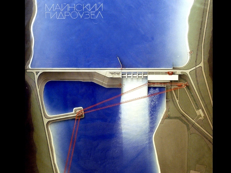
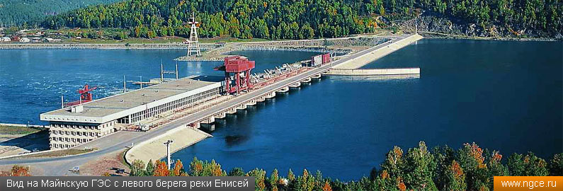
Maina's dam runs completely straight. Its low height (17-meter elevation change) allows a solid "brick" of concrete to resist water pressure through sheer weight. Such gravity dams rely exclusively on mass — not necessarily requiring pure concrete; brick, stone, and earth often suffice, provided adequate weight. Builders construct them substantially thick. Nearly all dams on plains or low-altitude mountains employ gravity designs. But deep canyons demand different approaches.
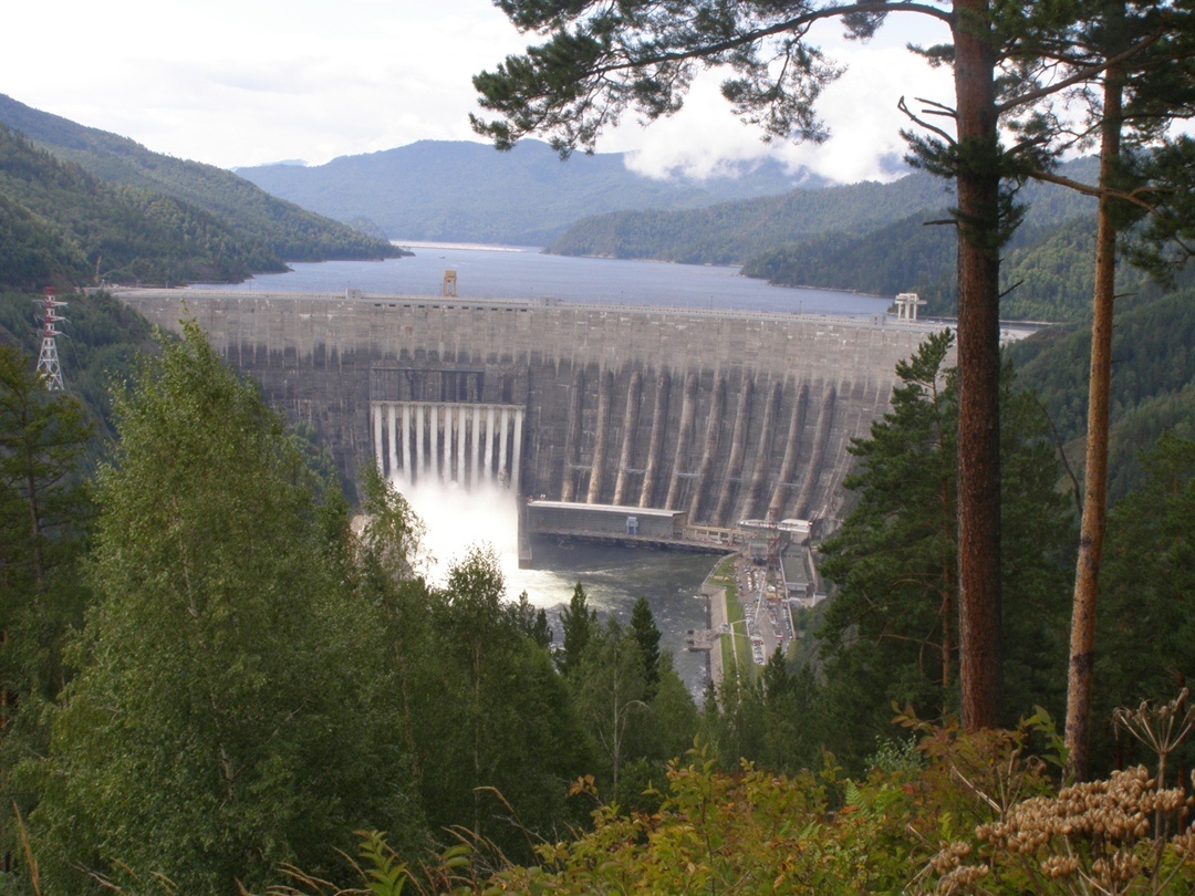
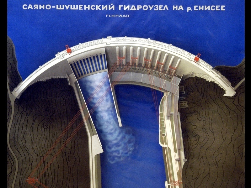
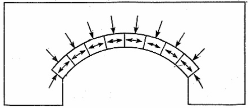
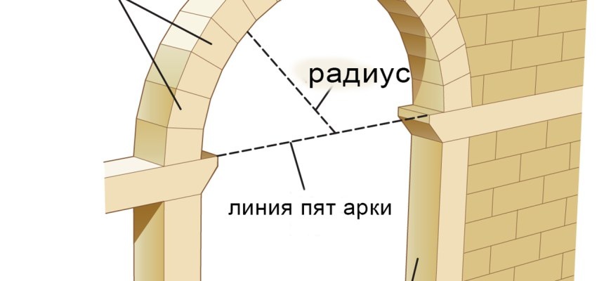
Sayano-Shushenskaya employs fundamentally different arch construction. Arches brilliantly distribute external pressure along curved surfaces. Trapezoidal bricks forming unified curves accept pressure and redirect it along the arc. For dams, this means water pressure diverts into surrounding mountains rather than pushing concrete backward. Mountain masses abundantly withstand Yenisei's force.
Another distinction: gravity dams resist pressure through sheer resistance to tension and bending. Arches naturally convert bending and tension into compression forces.
Critical point: Concrete undergoes slow chemical reactions — cement compounds change composition (setting) and harden. Rapid reactions occur initially; weeks later, people consider it finished. Actually, reactions persist for years, decades, centuries. Roman-era concrete continues setting today.
Compression strengthens concrete — the harder you squeeze, the stronger it becomes. Compression accelerates reactions and builds structure. Bending and tension cause cracking and deterioration instead.
Sayano-Shushenskaya's 240-meter elevation change exceeds many dams worldwide, though not the highest. However, its extreme width for an arch — over one kilometer along the crest — exceeds any pure arch's capacity. So engineers created a hybrid arch-gravity design: upper sections remained thin like arches; lower tiers grew thick and heavy like gravity dams. World builders had never attempted such hybrids, making this dam experimental. Consequently, builders incorporated excessive safety margins. How successful remains uncertain — continuous monitoring and preventive maintenance remain essential.
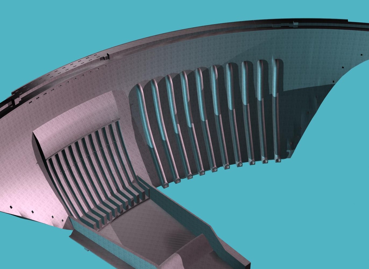
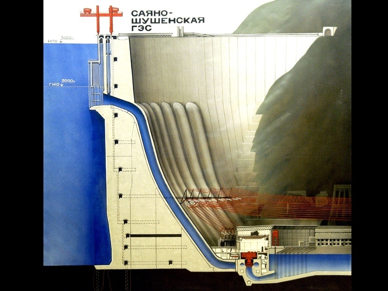
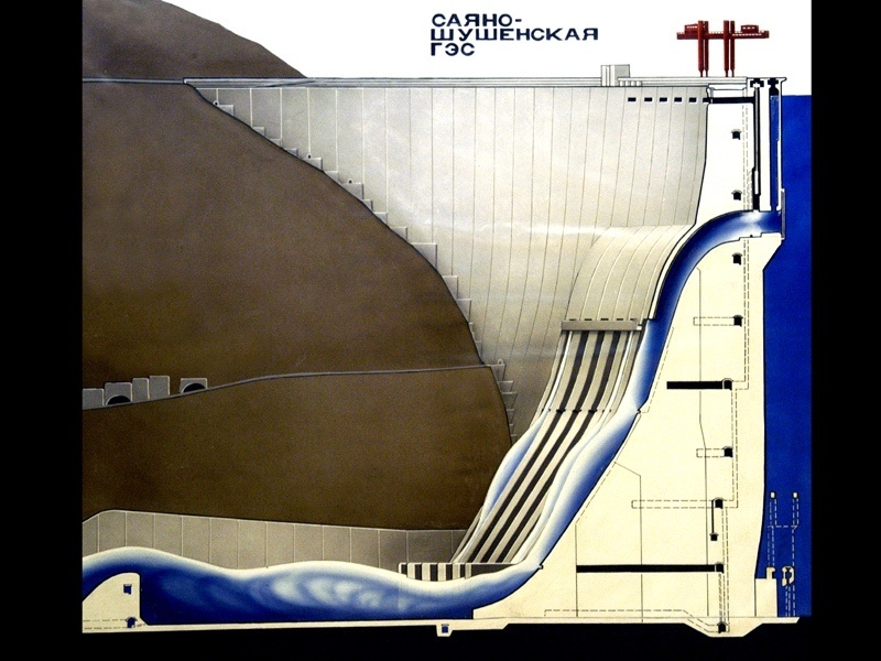
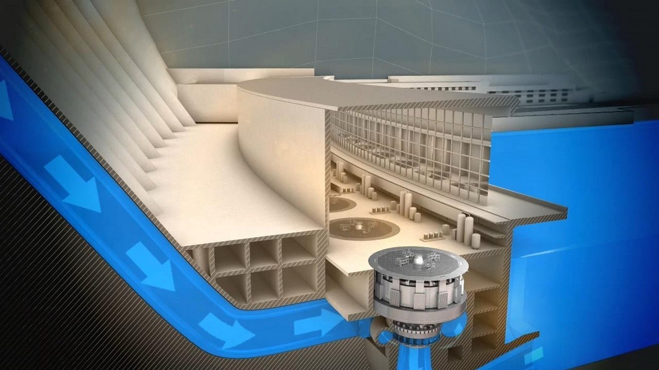
Upper reservoir water reaches lower reservoir via two paths: primarily through western intake pipes supplying turbine lobes with 240-meter pressure (24 atmospheres), spinning turbines and rotating shaft-connected generators. Excess water during floods exits through eastern spillways into the stilling basin, then downstream.
A third path — bank spillway — wasn't yet constructed in 2009.
From dam cross-sections, observe that spillways, water conduits, and machine halls represent merely external attachments to the arch's inner wall. Anything happening to these constitutes external events. The dam's perspective treats machine hall events as occurring downstream.
Part Two: Water and Hydroelectric Aggregates
Understanding power generator operation, turbine mechanics, and probable vibration causes requires minimal electrotechnical knowledge.
Electrical Generator Principles
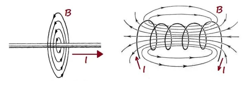
Place a wire beside a magnet — nothing happens while both remain stationary. Run electrical current through the wire; it creates surrounding magnetic fields. The magnet responds, attempting to align with field lines. Sufficient current strength might launch the magnet.
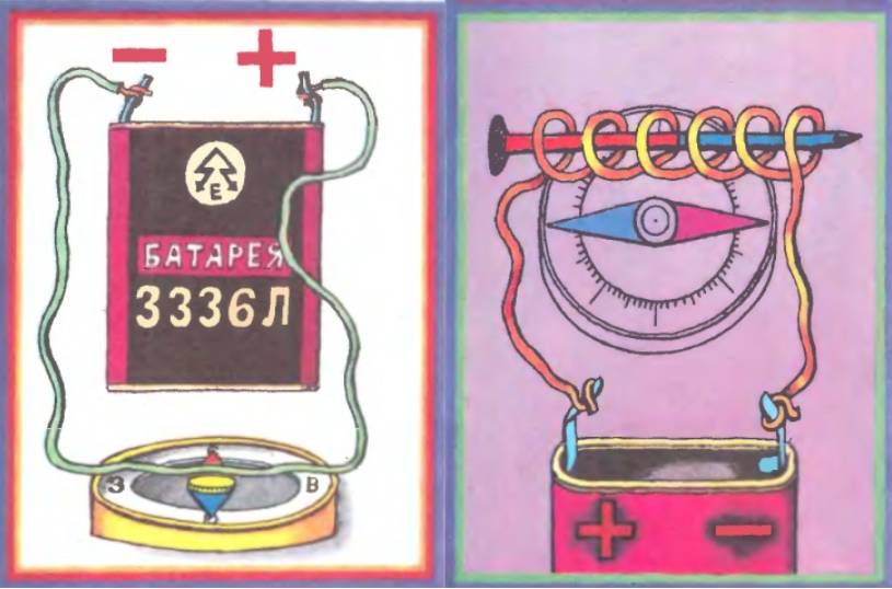
Strengthen this effect by coiling the wire into rings and placing magnets inside — increased effect. Multiple windings further amplify. Sufficient current creates such intense fields that magnets shoot out like cannon projectiles. (Wire insulation proves critical.)
Remarkably, this reverses: moving magnets inside coils generate electrical current. Halfway to converting magnet-plus-coil pairs into electricity generators.
Next: insert lengthy steel rods (extending beyond coil length). This achieves two objectives. First, ferromagnetic materials amplify internal magnetic fields several-fold. Second and critically, magnets move externally — ferromagnetic cores "capture" external magnetic field lines and direct them inside.
Finally: close the ferromagnetic cores into rings, place rotating magnets inside — instant alternating current generators! Industrial applications typically employ three coils rather than one, dividing rings into 120° sections, creating three current circuits. Call it three-phase generators.
For enormous generators, substitute ferromagnetic magnets with electromagnetic coils requiring direct current excitation, creating rotating but constant magnetic fields.
Shaft rotation speed remains standardized: 50 revolutions per second (Americans use 60) — the "50 Hz" figure marked on household outlets. Hydroelectric turbine rotors achieve approximately 142.8 revolutions per minute (slightly above 2 Hz). Such slow-speed generators employ multiple electromagnetic coils in rotors for required output frequency. The rotating component is the rotor; the stationary part is the stator.
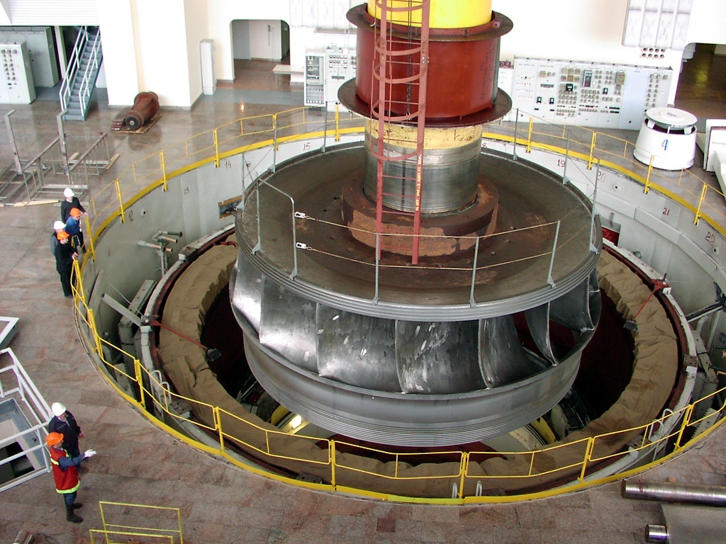
Generator Anatomy
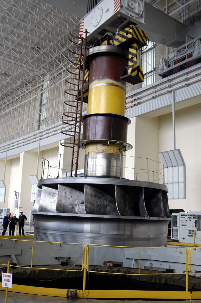
Before examining real generators, understand that generators remain useless without something rotating the shaft — turbines fulfill this role. The working wheel (turbine) serves one primary function: rotation at exact required frequencies.
This proves nontrivial: water column heights vary significantly annually. Droughts and floods occur. Seasonal snowmelt happens. Economic necessity sometimes demands higher discharge rates to refill downstream Krasnoyarsk reservoirs. Water levels constantly change. RusHydro documentation indicates Sayano-Shushenskaya turbines handle water pressures between 172 and 219 meters — variation of roughly fifty meters (five atmospheres). Despite such pressure fluctuations, turbines must maintain absolutely stable rotation frequencies for thousands of continuous hours.
This isn't everything: assembled turbine systems weigh diabolically — hence diabolically inertial. Launching aggregates into operation, reaching working speeds, maintaining frequencies, accelerating or decelerating, and halting aggregates demands diabolical precision — smoothly, gradually, without deviation from specifications.
This necessitates turbine speed management through mechanical systems crucial to generator survival. Below, they receive detailed analysis. For now, understand that working wheels weigh 154 tons.
Add 242 more tons for shafts with bearings and thrust pads. The shaft carries rotor generators totaling 912 tons. Top everything with a 379-ton aggregate cover.
Why enumerate component masses? To convey staggering numbers: water hammer forces sufficient to launch structure exceeding 1,300 tons (roughly two loaded mining trucks) twelve meters high in milliseconds!
Turbine Operation Mechanics
Now examine how unmanaged water flow converts into precisely-calculated turbine rotation.
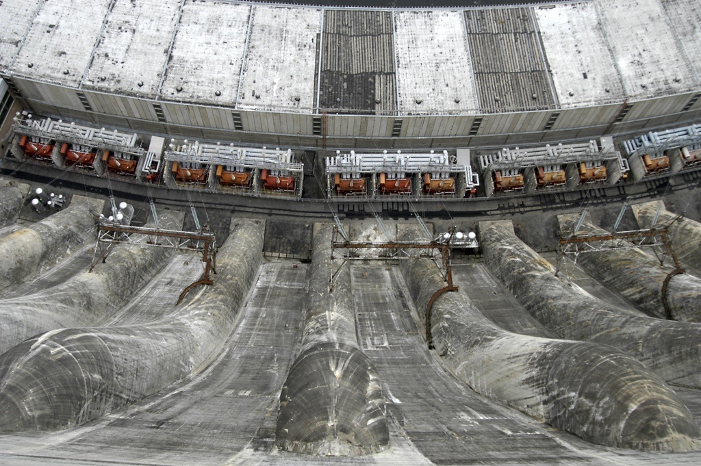
Step one: water from upper reservoirs enters intake structures, then rushes down concrete water conduits. Nearly quarter-kilometer elevation drop. Seven-point-five-meter constant internal diameter (15-meter external).
Step two: water reaches the turbine and conduit transitions into a spiral chamber ("snail" colloquially). It performs two functions: gradually reducing diameter from seven to three meters, further accelerating flow. Second and primarily, the "snail" spirals the flow, converting straight water into tightening spirals.
Why? Classical water wheels (familiar from medieval mills) demonstrate low efficiency — only one or two of six blades work simultaneously; others represent dead weight. Turbines within "snails" eliminate this inefficiency: spiraling water impacts all blades simultaneously, dramatically increasing efficiency.
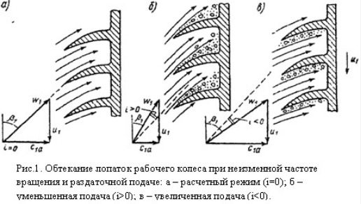
Step three: the "snail" isn't hermetic. Interior surfaces comprise latticed plates — these represent guide apparatus vanes. They ensure water strikes turbine blades at optimal angles ("angle of attack"), providing needed pressure magnitude and resulting turbine rotation speed.
Critical element: guide vanes aren't immobile. Each vane features individual servomotors enabling rotation and angle-of-attack adjustment. Guide apparatus vane rotation represents the primary aggregate management mechanism — analogous to automobile throttle positions.
Similarly with guide vanes: rotating clockwise increases water strike pressure on working wheels, increasing rotation speed; counter-clockwise decreases speed.
Managing guide vane rotation represents damnably responsible work: vanes must synchronize perfectly, rotating simultaneously at precisely-calculated degree fractions per central command. Only automated control systems achieve such synchronization.
Vane desynchronization or suboptimal angle opening create seriously adverse conditions.
Primary Catastrophe Suspects
Transitioning from established facts to contentious terrain featuring expert disputes.
Eighty M80 bolts (approximately 8-centimeter diameter) secure the aggregate cover. Each bolt carries a nut requiring not merely threading but substantial tightening — tensioning must resist formidable water pressure. Simultaneously rupturing all 80 bolts proves impossible; powerful vibration must progressively loosen them.
Where does vibration originate? From irregularities of any kind: misaligned turbine center, compromised centering during operation, bearing looseness and resulting shaft run-out, uneven water flow through conduits, desynchronized guide vanes... possibilities proliferate.
Critically, vibration doesn't manifest instantaneously. Shafts initially oscillate slightly, then amplify or diminish, through ordinary resonance: interactions between two oscillations. When frequencies approximate closely, rapid oscillation amplitude increases (mechanical resonance). What barely vibrated suddenly shakes violently.
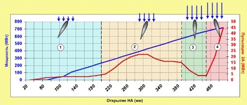
Over Sayano-Shushenskaya years, engineers developed frequency danger diagrams. Work instructions explicitly marked forbidden-operation frequencies: avoid prolonged aggregate operation at these frequencies.
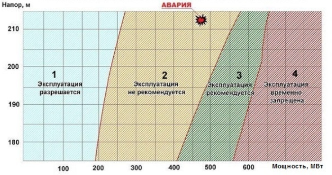
The investigation document states: "Turbine operation in Zone II experiences severe hydraulic shocks within flow sections and significant noise; dynamic characteristic levels remain unacceptable..."
At aggregate #2's location during the disaster, somewhere around 320mm guide apparatus opening occurred — exactly where maximum pulsation manifested.
State commission materials alleged bolt deterioration from material fatigue. Independent researchers dispute this, claiming catastrophe forces exceeded even pristine bolt capacity.
Vibration Mechanisms
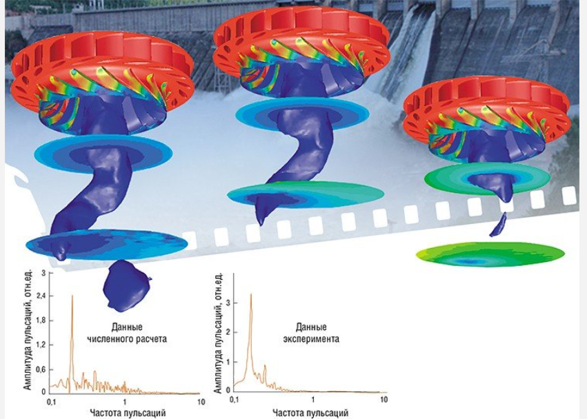
Candidate #1 — Cavitation: Water moves dramatically at high speeds. Bernoulli's physics proves that increased flow velocity decreases internal pressure. Rising turbine speeds create such low-pressure regions near shafts that dissolved air nucleates bubbles — cavitation phenomena.
Water boils under pressure reduction at low temperatures. Evolved bubbles merge into gaseous filaments. Turbines rotate not in water but air. Consequences: blade destruction and shaft imbalance.
Candidate #2 — Surge (Pompage): A phenomenon familiar to aerospace engineers. Surge is unstable engine operation causing gas-dynamic instability, producing compressor inlet counter-flow, sudden thrust loss, and powerful vibration capable of destroying engines.
Aircraft suffer hundreds of destroyed engines from surge. If this phenomenon occurred in water (far denser medium) instead of air, resulting destruction scales become staggering.


Which mechanism triggered excessive vibrations remains disputed, though hypotheses coexist complementarily.
Chain Reaction
Recall generator construction: rotors contain powerful electromagnets. Stators comprise coils generating electrical current. Stators produce secondary magnetic fields forcefully attempting deceleration. Preventing stalling demands powerful rotational forces.
During the catastrophe night, aggregate #2 repeatedly experienced extreme vibrations eventually causing shaft run-out.
Recovery remained possible! Immediate action: withdraw from dangerous resonance frequencies or fully shut water intakes. Instead, at 08:13:24, the oscillating shaft impacted stator windings, severing coil connections. Short circuits ignited and electromagnetic braking collapsed!
Critically, shaft dynamics involved equilibrium between accelerating water pressure and electromagnetic braking. Suddenly, the deceleration force vanishes...
Automobile analogy: accelerate uphill, then shift to neutral while maintaining throttle. The engine roars maximally, tachometer needles slam redline.
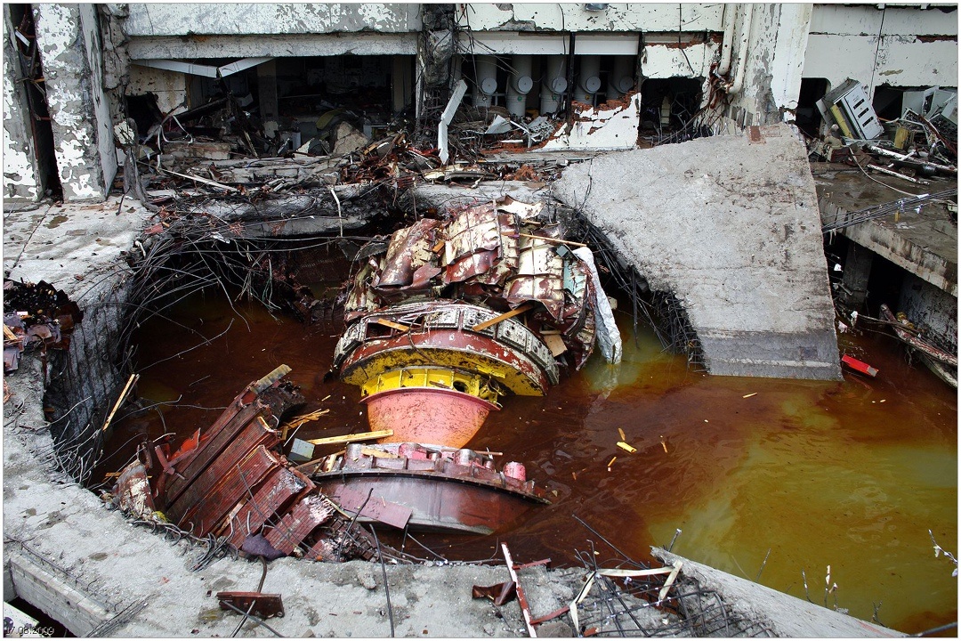
Aggregate #2, already unstable, shaking so violently that seismographs registered disturbances 4 kilometers away, catastrophically accelerated! Vibrations intensified exponentially, snapping bolts progressively. The 379-ton cover slipped, the 1,300-ton assembly launched twelve meters, crashed down, and fractured concrete foundations like an enormous mill.
Catastrophically, water flooding the machine hall immediately shorted electrical distribution. All nine remaining operating aggregates lost magnetic fields simultaneously — each became a bomb. Aggregates #7 and #9 disintegrated completely; others sustained extensive damage.
FAQ
What is this article about in one sentence?
This article explains the core idea in practical terms and focuses on what you can apply in real work.
Who is this article for?
It is written for engineers, technical leaders, and curious readers who want a clear, implementation-focused explanation.
What should I read next?
Use the related articles below to continue with closely connected topics and concrete examples.