Analog CO₂ Sensor with a Vintage Gauge Needle, ESP32, and Tasmota
A DIY smart home CO₂ monitor built inside a repurposed IKEA alarm clock, using a SenseAir S8 sensor and an automotive stepper motor to drive an analog needle gauge — all running on Tasmota firmware with custom Berry scripts and a hand-soldered PCB.
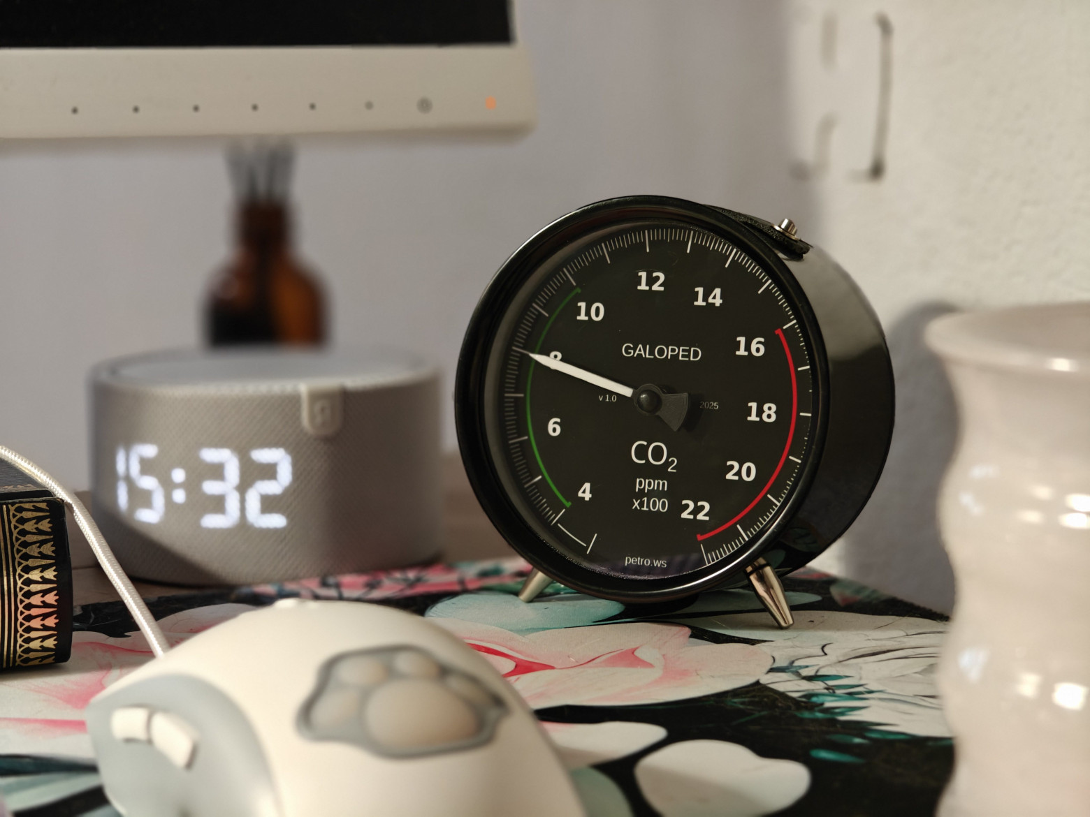
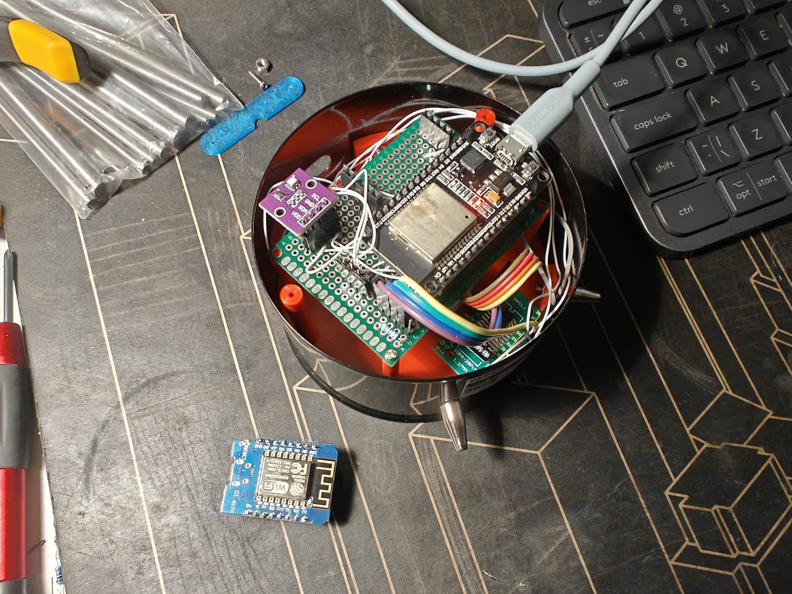
I wanted a CO₂ sensor for my home that would show the current reading at a glance — no screen to wake up, no app to open. Something with a physical needle, like an old instrument panel. This is the story of how I built the Galoped-Dekad: an analog CO₂ gauge powered by ESP32, driven by Tasmota, and housed in an IKEA DEKAD alarm clock.
Why Analog?
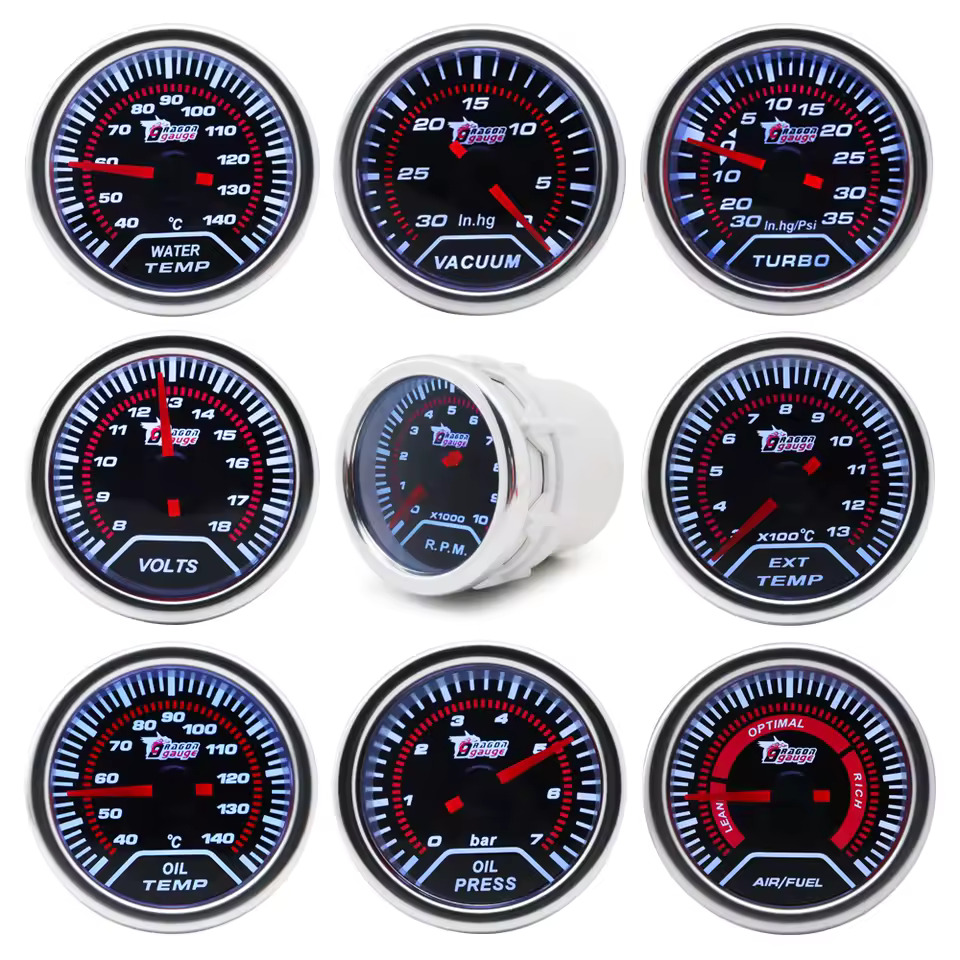
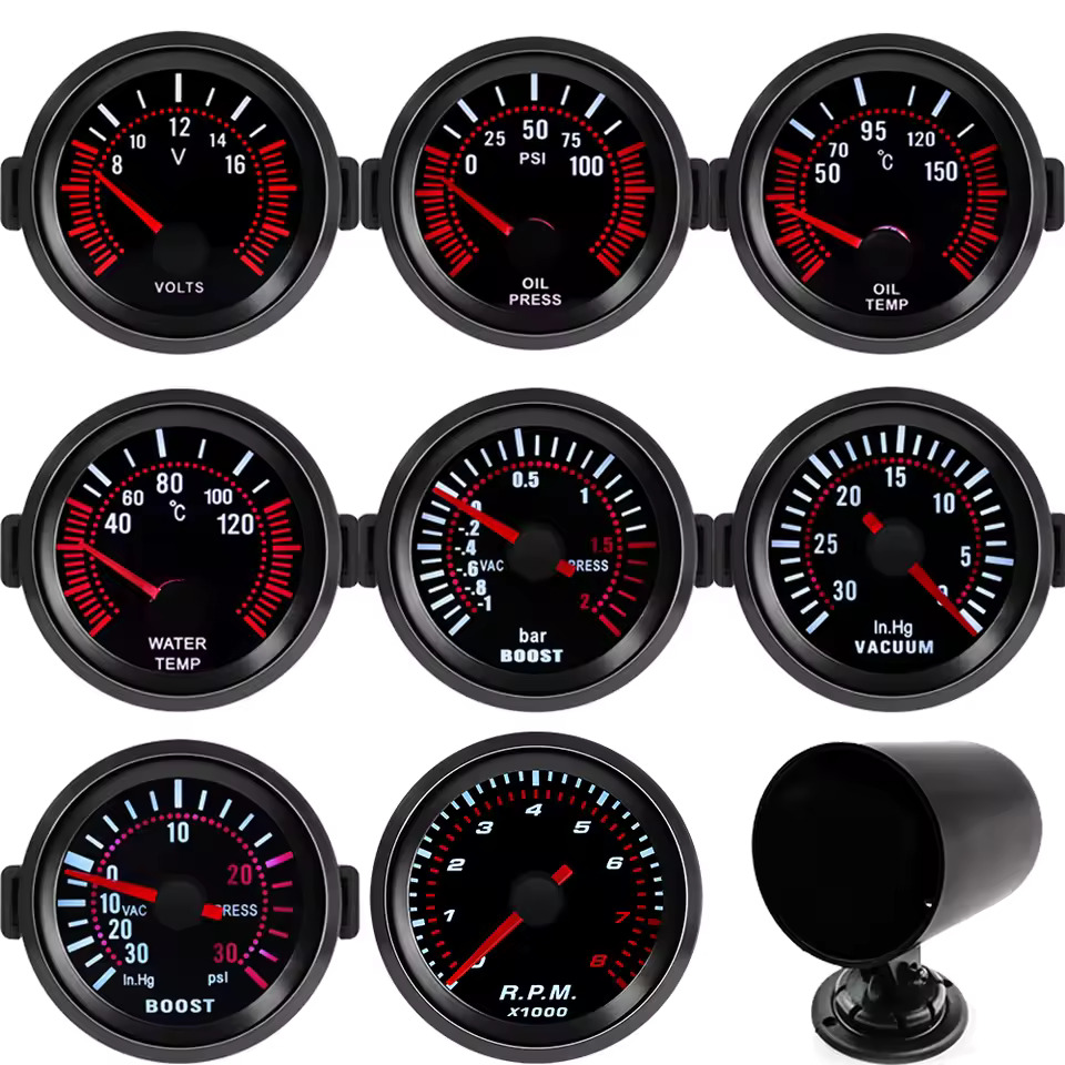
Digital displays are accurate, but they require your active attention. An analog needle gives you peripheral awareness — you glance across the room and instantly know whether the CO₂ is in the green zone or creeping toward 1500 ppm. Aviation instruments, vintage lab meters, automotive dashboards: they all understood this. I wanted that aesthetic combined with modern smart home integration.
The device series is named Galoped — a portmanteau in the IKEA tradition, combining unrelated words. The Dekad suffix refers to the donor enclosure: the IKEA DEKAD alarm clock, whose face is the perfect size for a CO₂ dial.
Key Components
- CO₂ sensor: SenseAir S8 — NDIR (non-dispersive infrared), UART interface, 400–2000 ppm range, low power consumption
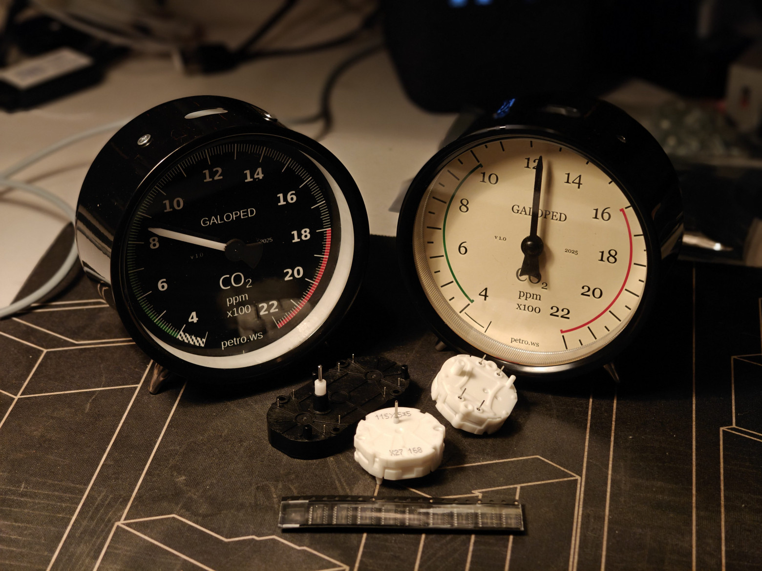
- Gauge motor: X27-168 automotive stepper motor — the same type used in car instrument clusters worldwide
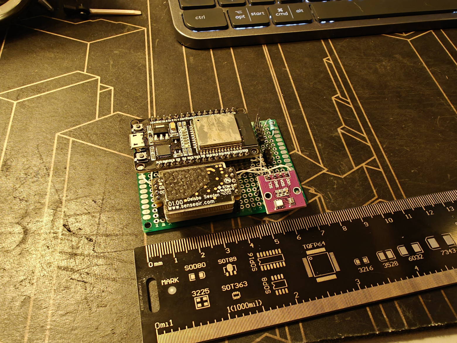
- Microcontroller: ESP32-WROOM-32 — dual-core, Wi-Fi, runs Tasmota
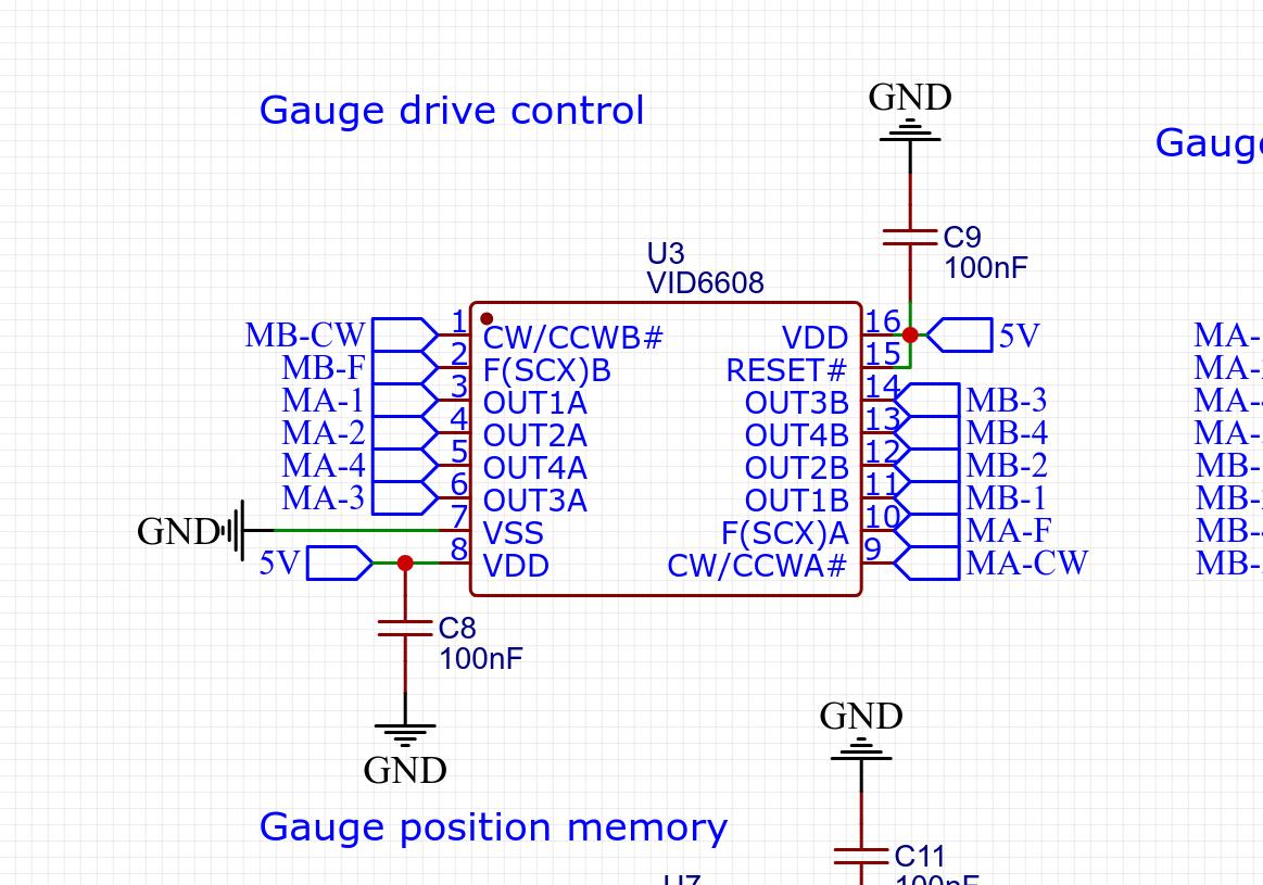
- Motor driver: VID6608 chip — designed specifically for X27-series gauges
- Climate sensor: AHT20 + BMP280 module — temperature, humidity, pressure
- Memory: MB85RC04V FRAM — non-volatile, for storing needle position across reboots
- Enclosure: IKEA DEKAD alarm clock (donor) + custom 3D-printed parts
- Firmware: Tasmota with custom VID6608 driver and Berry scripting
Developing the Tasmota Driver for VID6608
The X27-168 motor is a bipolar stepper with two coil pairs. Driving it correctly requires precisely timed microstep sequences — something the existing open-source SwitecX25 library handles, but with bugs that caused occasional stutter and incorrect homing behavior.
I rewrote the driver from scratch as a Tasmota component (submitted as PRs #24153, #24189, and #24218). Key engineering decisions:
- FreeRTOS task for motor control, running independently of the main Tasmota event loop — this eliminates jitter caused by Wi-Fi and MQTT activity
- Mutex-based synchronization between the motor task and the Berry scripting layer, preventing race conditions when CO₂ readings arrive mid-sweep
- Configurable step timing — the X27-168 needs approximately 1.2 ms per microstep for smooth movement; faster rates cause missed steps and position drift
- Homing routine on startup: the motor drives to the physical stop, then advances to the stored FRAM position
The driver is also available as a standalone Arduino library: arduino-vid6608.
PCB Design
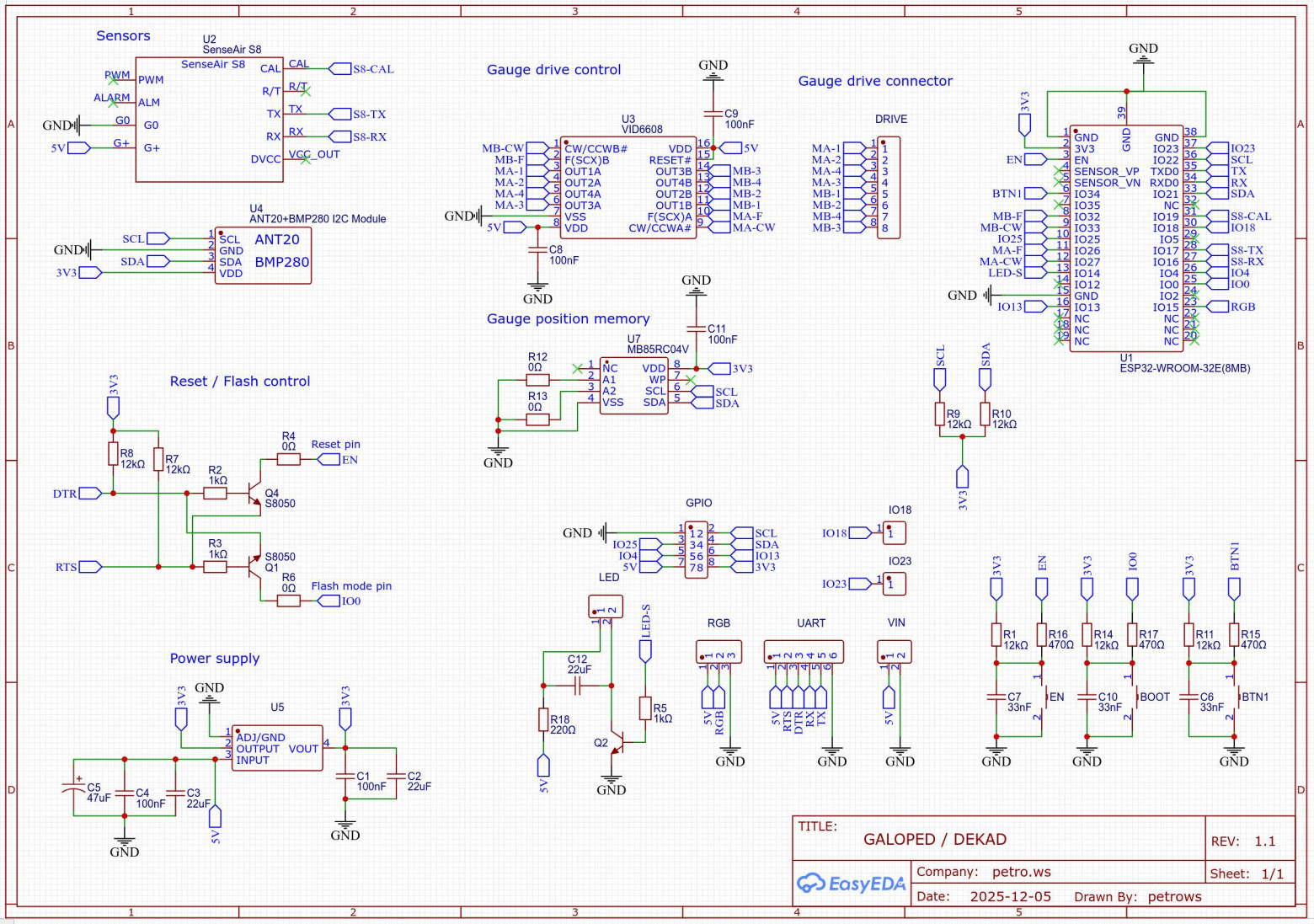
The main board is a compact two-layer PCB designed in EasyEDA (project available on oshwlab.com/petrows). It integrates:
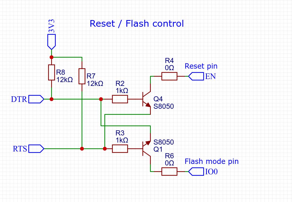
- Reset circuit — RC network with a supervisory IC ensuring clean power-on reset
- VID6608 motor driver with decoupling capacitors and flyback diodes on the coil outputs
- I2C expansion header — for AHT20/BMP280 module and the FRAM chip
- FRAM circuit — MB85RC04V on I2C address 0x50, used to persist needle position so reboots don't cause a full sweep from zero
- UART header for SenseAir S8 connection
- WS2812B data line for addressable LED backlight (40 LEDs in the backlit variant)

3D-Printed Enclosure
The IKEA DEKAD clock provides the outer shell and glass face. Everything else — the internal structure, motor mount, needle, bezel, sensor caps, and rear panel — is 3D-printed in PLA.
- Needle: Printed flat, then painted with silver paint. The X27-168 shaft press-fits into the hub.
- Gauge bezel: Two-layer design — inner layer with cutouts for light diffusion, outer decorative ring. This creates a halo effect around the dial face.
- Sensor housing: A small cap on the rear panel allows air circulation around the SenseAir S8 while protecting it from direct airflow that would cause false readings.
- Rear panel: Houses the USB-C power input, a status LED, and the PCB mounting standoffs.
Backlight Iterations
Getting the backlight right took three attempts:
- Filament LED strips — warm and lamp-like, but uneven hot spots behind the dial
- Plain SMD LEDs — brighter, but harsh and directional
- WS2812B addressable RGB LEDs (40 LEDs) — individually controllable color and brightness, allowing smooth color transitions based on CO₂ level (green → yellow → red)
A 3D-printed diffuser ring sits between the LED ring and the dial face, softening the output to a uniform glow. Tasmota's Scheme and Color commands control the LEDs directly via MQTT.
Dial Design
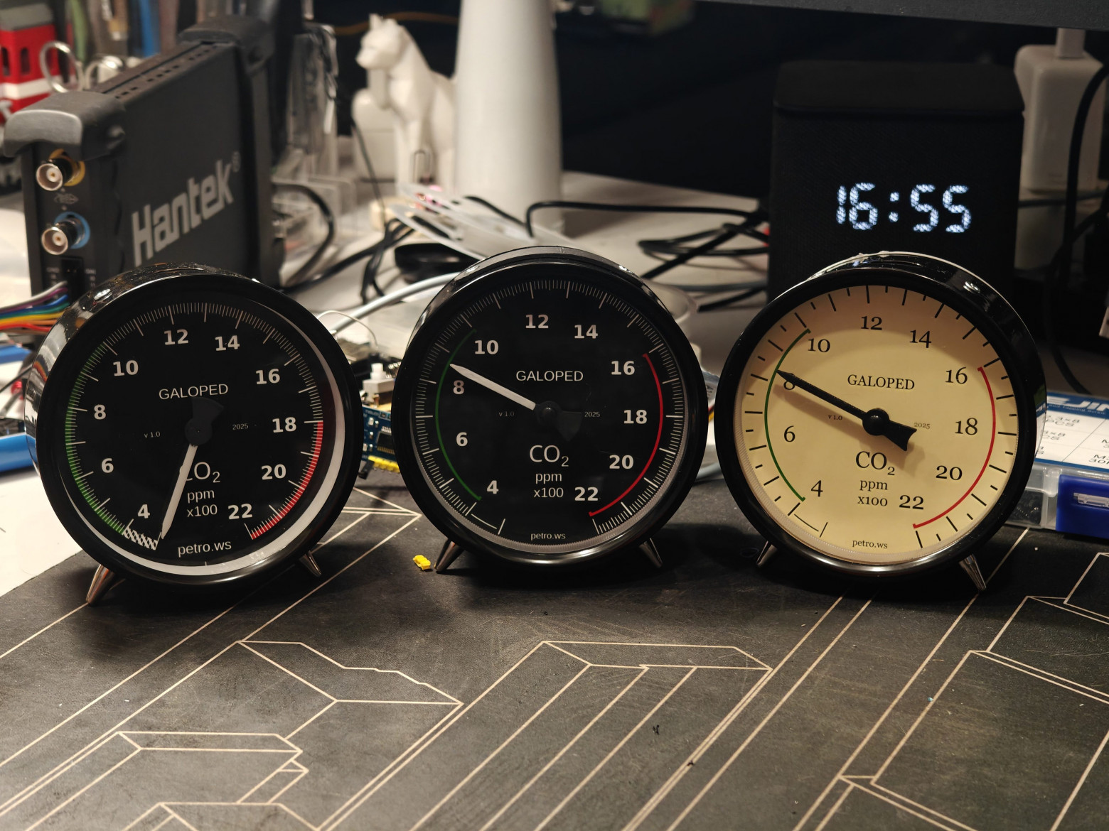
Dials were drawn in Inkscape and printed on photo paper. Two styles are available:
- Aviation style — thin needle, black background, white markings, technical font. Modeled after aircraft altimeters.
- Retro style — broader arc, cream background, brown markings, period-appropriate typography.
The CO₂ scale runs from 400 to 2200 ppm, with a 15° dead zone at each end to prevent the needle from hitting the mechanical stops during normal operation. The color zones are:
- 400–800 ppm: green (fresh air / outdoor levels)
- 800–1200 ppm: yellow (acceptable, ventilate soon)
- 1200–2200 ppm: red (poor air quality, ventilate immediately)
Firmware Configuration
The firmware is standard Tasmota with the following additions in user_config_override.h:
#define USE_VID6608
#define USE_AHT2x
#define USE_BMP
#define USE_SENSEAIR
#define VID6608_RESET_ON_INIT false
#define WS2812_LEDS 40
The Berry script (autoexec.be) handles the logic: reading CO₂ values from the SenseAir S8, converting them to needle positions, and persisting the position in FRAM so the needle resumes from the correct position after a reboot.
The position conversion formula is straightforward:
drivePos = 180 + ((co2_ppm - 400) * 2)This maps 400 ppm → position 180 (leftmost) and 2200 ppm → position 3780 (rightmost). The factor of 2 is calibrated to the specific gear ratio of the X27-168 motor and the 270° sweep of the dial.
FRAM read/write functions in Berry ensure that if power is lost mid-reading, the needle resumes its last known position on the next boot rather than sweeping all the way from zero — which would be both ugly and mechanically stressful.
Home Automation Integration
Tasmota publishes sensor data via MQTT in standard JSON format. An example OpenHab configuration binds the topics:
// CO2 reading
MQTT topic: tele/galoped-dekad/SENSOR
JSONPath:   $.SenseAir.CarbonDioxide

// Temperature
JSONPath:   $.AHT2X.Temperature

// Humidity
JSONPath:   $.AHT2X.Humidity
The same MQTT topics work with Home Assistant, Node-RED, and any other automation platform. The WS2812B LEDs can be controlled independently via the standard Tasmota light commands, allowing the hub to set backlight color based on CO₂ thresholds.
Bill of Materials and Cost
Total hardware cost per unit is approximately €50, with the SenseAir S8 accounting for the majority (~€35 alone). Breakdown:
- SenseAir S8 CO₂ sensor: ~€35
- ESP32-WROOM-32 module: ~€3
- X27-168 stepper motor: ~€2
- VID6608 driver + passive components: ~€1
- AHT20 + BMP280 module: ~€2
- MB85RC04V FRAM: ~€2
- PCB fabrication (JLCPCB, 5 pcs): ~€5 total (~€1 per board)
- IKEA DEKAD clock: ~€5
- 3D printing filament, misc hardware: ~€3
This does not include 3D printer amortization or labor time.
Planned Improvements
- Upstream FRAM support into Tasmota core (currently requires Berry workaround)
- Redesign the sensor connector for easier access during calibration
- Replace the VID6608 breakout board with direct PCB integration
- Add a small status LED visible on the front face
- Switch to USB-C on both the main board and sensor connector
Source Files
Everything is open source under GNU GPLv3:
- GitHub repository: github.com/petrows/smarthome-galoped-dekad
- PCB projects: oshwlab.com/petrows (main board and VID6608 breakout)
- Pre-built Tasmota firmware: available in the GitHub Releases section


